Update for the week of March 15 – March 21

On Tuesday, we finished our connection from the main PCB to the Arduino shield. Originally, we were going to to striped the IDE ribbon cable and solder it on the Arduino shield. However, we found out the wires are to weak to be secured on the shield. Instead, we connected the IDE ribbon cable to a IDE socket on the shield. This is more secured and easier to disassemble and reassemble the connection.  In addition, we purchased a 3 meter long L shaped aluminum from the machine shop and attached to our platform as it will be our side guard.


On Thursday, we fully tested our PCB circuit with all components attached to it. It is fully functional, however, we need to re-collaborate our scale to obtain a new equation. Furthermore, we also received our ramp from the machine shop. We still need to buy the side guard for the ramp and  multiple hinges to attached the ramp to the base.


On Saturday, we finished the design for our circuit box and attached it to the pole. We also filmed the remaining part of our video. We still need to put in some ppt slides in the video, and we are expecting to be done by next Tuesday. In addition, we also started preparing the draft for poster, and it will be sent by next Tuesday.


Today, we also received our ramp from the machine shop

Update for the week of March 8 – March 14

On Tuesday, we met with Navid, and gave him the following updates.

  • We will be filming our client while he answer our questions on Thursday
  • the ramp is still in progress
  • the components we bought on last Thursday
  • we will be making the holes on the box for LCD, push button and the toggle switch at the machine shop

On the same day, we went to machine shop and asked Mark for a sheet of metal that we will be covering our platform. We decided not to bend the metal, as we don’t have the proper machine that is able to do this. Instead, we will be covering the side with other material. Therefore, Mark cut the metal with a size of 800mm*1200mm. This cost of metal will be charged to our Capstone financial account directly.

After we received our invoice for the platform we had made in the machine shop. The cost was $80 for 2.5 hours of work, which brings our running total to $618.65. This does not include the ramp we are having made, or the sheet of metal we purchased from the machine shop today, since we have not been charged for those items yet. We expect to be charged another $100 for them. We also estimate that we will need another $150 for miscellaneous items such as material to cover the sides of the scale, metal to cover the ramp, sideguards, etc. Therefore, we asked the department for budget extension.

On Thursday, we met with our client and film him while he answers the following questions:

  1. Please introduce yourself.
  2. Describe who Tetra is and what they do.
  3. Why did you suggest this project to UBC?
  4. How do you think not weighing yourself can affect your health?

On the same day, we received our PCB. So we started to test the PCB one part by one part, making sure there is no short circuit or mistake. We found one mistake regarding the size of the INA. The holes for INA are too far apart. So the INA IC wont able to fit in. We solved this mistake by stacking a “right size” socket to a bigger socket which can fit into the holes. We also soldered the socket for LCD, LCD driver, IDE, and regulator.  In addition, we received a email respond from Professor Gopalakrishnan, asking for a list of the things we bought, and the things we are buying.

On Saturday, we tested the PCB with adapter, power button, INA, and the platform with the load cell, and it showed the signal has successfully being amplified. In addition, we started making our video. It is almost done. We still need to put our final product into the video.  Our budget extension has approved by the department!!!


Update for the week of March 1 – March 7

On Tuesday, we met with Navid to inform him our progress:

– The PCB has been send for fabrication.

-Some suggestions regarding how to assemble the PCB were given.

  • Solder the PCB parts by parts
  • test if there is short circuit between ground and vcc
  • put the ICs after
  • it’s better to use socket than soldering the ICs directly to PCB

On the same day, we discussed our storyboard and decided the basic idea how we are going to film our video, and also decided the questions we are going to ask our client during filming.

On Thursday, we obtained the legs for our platform, and we then started to design our ramp with a height of 8.5 cm. After discuss with Mark, some designed techniques were given. Therefore, we designed the ramp with three right triangles as a stand, and a piece of a wood on top of its hypotenuse. It reduced the weight and the material used.

On the same day, we went to Lee’s Electronic after our short meeting at school. We purchased the following items:

  • plastic box for our circuitry
  • socket for LCD, regulator, and INA
  • Arduino prtotosheild
  • Solder iron


Update for the week of February 23 – March 1

On Tuesday we met with Navid to follow up with the progress of our project. The following were discussion in the meeting :

– Address certain issues regarding about the PCB. Navid suggested that we the connector to connect all the inputs and outputs to the Adruino instead of the ATMega chip because instability and noise from the surrounding may raise concerns with the signals transmitted between the micro controller chip and the other parts of the circuit.

– To have both parts ( Main PCB and LCD PCB) to be designed on the same PCB board.

– Heat sink for power regulator- In case of too much heat dissipation due to high power, a small metal piece may be considered to be added behind the voltage regulator chip. Current has to be measured to know the power dissipated.

-Traces on the PCB to have minimum clearance of 0.4mm.

-Holes to be at least 1mm and pads to be 2mm.

We have also screwed both (top and bottom) layers of the platform.

On Friday, WengFei has scheduled with Navid to go through the PCB design again before sending it off for fabrication. Minor changes to the circuit has done and has been finalized by the end of the day.

On Saturday, PCB was ordered and the designed was sent to 3PCB in China for fabrication. The manufacturing of the PCB will take about 2-3 days and an additional few days for shipping.


Update for the week of Feb 9 – 15, 2015

On Tuesday , we had our 2nd prototype due. We presented our prototype in front of Cristian, Eric ( our client) and Navid. The presentation and live demo went well. After the presentation, Cristian, Navid and Eric has brought up a few points regarding our prototype and our plans to move forward with our final prototype. The following are the list of points raised during our discussion:

– The suggestion of building a Side Guard for the ramp for safety of the user.

– Connectors on the PCB to be re-positioned (to be placed at the edge).

– Further research needed to be done on the mobility and storage of the platform.

– Duane (our client) will make a final appearance in the final prototype. Maria will get him the video or pictures to Eric for our current prototype thus far.

-– Wheel gap on the platform to be designed  so that the user can easily position his/her wheelchair when using the weigh scale.

On Thursday, we met up to discuss about the steps to be taken for our final prototype before reading break begins. We also discussed the parts to buy over the break. The following is our meeting agenda:

1. Fabricate PCB: we need to finalize our amplifier circuit, measure the current of our entire system, decide on an adapter, decide if we are using the small arduino chip, add reset functionality, finalize PCB design

2. Buy rest of parts (reset button, sealant spray, wood, pole, plastic box, bolts, screws, etc)

3. Build ramp

4. Build circuits enclosure

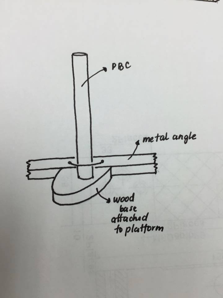
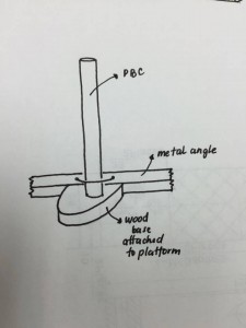
5. Figure out how we’re going to attach the pole to the platform

6. Cut out the grooves on the base for the back wheels

7. Spray sealant on the wood!

8. Get metal sheet (design it with side guards)

9. Bolt platform top to load cell

10. Bolt platform pieces together

After the meeting, we have agreed on certain solutions and steps needed to be taken:

-– We have finalized the parts needed to buy over the weekend.

-– PCB: we are leaving the option open for the implementation of the microcontroller chip as well as the connector for adruino for our PCB design. Oscar: provide connections for the chip and reset button.

-– Ramp Gap: We couldn’t really decide on the groove (ramp gap) because the groove needs to be done on the wood, then covered with metal. The main concern is that it may ruin the platform and make it hard to calibrate. We will discuss more about the matter in the coming meetings.

-– Sealant could be applied as soon as we get it; this weekend or during the break.

-–  Bolting the load cell to the platform, bolting platform pieces together can be done only after break.

-– Building the ramp and enclosures is left for later since  the height of the ramp will change depending on the metal sheet. As for the enclosures, it depends on the PCB size which is still not finalized at the moment.

4. PCB is still not finalized as we are not yet certain about the adapter and voltage regulators and how much voltage we need.

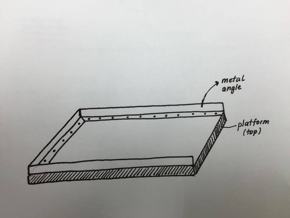
We have also came out with a rough sketch for our Safe guards for the platform and the pole for the circuit enclosures:

ramp

pole

Over the weekend (Saturday and Sunday):

We met up to buy parts needed for our final prototype. We have manged to buy:

from Lee’s:
1. Adapter 9V
2. Reset Push Button
3. Voltage Regulator (LM317/LM7805)
4. 10 pin socket and screw terminal.

Hardware Store (Canadian Tire on Cambie & Kerrisdale Lumber)
1. Bolts for the load cell (M6 countersunk crew)
2. Wood sealant/stain for the platform;

List of items yet to buy:

4. Stands for the platform/legs;
5. Metal sheet (120cm x 80cm);
6. Metal angles for the guards (350 cm);
7. PVC pipe for the pole (150 cm);
8. A piece of wood for the pole;
(We gonna ask if Mark can provide us with 5,6,7,8 from the machine shop)


Update for the week of Feb 1-8, 2015

On Tuesday we met with Navid and Cristian to present a dry run for our second prototype. The following were the advice given and issues discussed by them :

– Have all the presentation slides numbered.

– Pronounce the word ” Centimeter” instead of Cm – need to be consistent with the terms.

– Further elaborate and clarify the power regulator in the slides.

– PCB design: found problems with the connectors.

On Thursday we started to calibrate our weigh scale using a wheelchair we got from the wheelchair rental company. We took a number of readings and plotted a graph in Excel to obtain the equation needed for the weigh scale. We tried different types of graphs to fit all the data points. Since the upper layer is not bolted, a small layer of metal piece was used to fit in the hollow space between the load cell and upper platform for better measurements.

On Saturday we met up and worked on the calibration of the load cell using the wheelchair from the Biomed lab . Since it is a different wheelchair (different weight and placement of the wheels ),  we used previous equations from the wheelchair we rented to test it on the  Biomed lab wheelchair. There is a need for recalibration. Apart from that, we finalized the presentation slides and WengFei and Michael practiced the presentation.

Update for the week of Jan 25-31, 2015

On Tuesday we met with Navid and talked more about our current situation:

– Our design was in the progress of being built

– PCB designs were on the way

– Parts about to buy

– Presentation

On Thursday we obtained our platform from the machine shop, we did some further processing to the platform so that the center will bend more. Instead of four long sticks laminated to the sides we cut off some materials so that only the corners will support the upper base.

On Saturday we met up and worked on the calibration of the load cell, we found the load cell to generate a signal when force is applied to the base, we might be adding an extra amplifier in order to obtain a better signal.


Update for the week of Jan 18-24, 2015

This week our main focus was building the platform. On Tuesday we met with Navid and discussed about the most recent design of our base platform and the progress of the PCB board.

We redesigned our platform a couple times from Monday to Wednesday and our wood arrived on Tuesday. We then talked to the Mark from machine shop about the building of our platform. We submitted a ticket and with a couple back and forth with Mark the platform is now underway to get made.

Currently we are waiting on the platform and to calibrate the load cell, and cutting some edges on the platform to make better fit for the load cell and circuits. PCB design is also moving forward with changing the design for the wires to not overlap.


Update for the week of Jan 11-17, 2015

On Tuesday, we met with Navid and were given some help with the PCB design and circuitry:

– We will be using extensions for the LCD Screen and other components to have better placement in the circuitry box

– Possible new programs and ways to design the circuit on the PCB board

We also got to meet with a professional mechanical engineer who looked over our design and gave us many ideas.

We took the Machine Shop tutorial on Wednesday and got some more feedback regarding our design. We have decided to make the base out of wood and have a sheet of steel on top of it.

We completed the platform design on Solidwork and will be obtaining the materials this weekend and possibly finish building it by the end of next week.

The addendum is finalized and has been sent.

The tasks for this weekend have been assigned:

Maria will be buying the wood and get it cut to size for the platform

Oscar will be finalizing the base design

Michael will be drawing the enclosures for the circuits

Mustafa and Weng Fei will be making the draft schematics in Altium