Monthly Archives: April 2018

Final Possible Body Design (Sean, Week 11)

Since this was the week of our COGS 344 presentation, I spent most of it collecting past robot designs and preparing to present. The currently printed body is not able to display the behaviors I had hoped, so I’m planning on bringing it in without the motors and relying on my video of the wood-block prototype to illustrate the intended range of motion. I also spent a lot of time leading up to the presentation trying to finish a better 3D model to demonstrate in my presentation and hopefully use in the future.

The “ears” in this image are there just to illustrate what this would look like if printed with attached ears.

Despite the fact that most people I have asked have seen my prototypes as heads rather than bodies, I have chosen to commit to creating a body instead for several reasons. First, this design is more mechanically consistent with the wood-block prototype i created earlier. The strings that control the ears full backward rather than down as they did in my previous print. That downward motion meant that the ears did not behave as expected. Beyond that, using a head as a model presents difficulties in terms of later testing. A disembodied head on a table is weird, and would need to be incorporated into a body of some kind. Designing an entire body instead eliminates this problem.

At the time of my COGS 402 final deliverable, this is the most recent prototype I have, and the result of many weeks of constant sketching, prototyping, and failing across a number of physical and digital mediums. More than anything, I would say this experience has illustrated to me how important the “rapid” part of rapid prototyping is. The amount of time I spent struggling to learn to use 3D modelling tools to realize my ideas dramatically slowed my progress toward creating a usable robot. One of my personal goals for this project was to learn how to 3D model, and in that way I was successful, but I probably should have spent more time on lower fidelity prototypes before devoting so much time to learning an entirely new tool from scratch. Regardless, my time in SPIN Lab was an amazing and fun learning experience, and one which I would highly recommend to future 402 students.

Rebuilding the Ears (Sean, Week 10)

The temporary wooden base I was using to hold my model ear to the screw attaching it to the body has finally broken. This means I need to quickly build a new model so that I can continue making sure that my current model is viable before designing behaviors and potentially printing a final body. The new ears are built around a hollow aluminum tube attached to a screw. The fact that it’s hollow makes it much easier to achieve the flat shape i need than the wood, which I had to sand down by hand.

Reconstructing the ears has also given me the opportunity to reconsider the mechanism I’ve been using to attach them to my past body designs. Previous designs relied on a tightened bolt to hold the ears in place inside a channel along the top of the body. This worked at the start, but the constant rotation of the ears meant that the bolts would eventually loosen, relying instead on the tautness of my control strings to hold the ear in place. Crimping aluminum directly onto the screws means that the rotation shouldn’t have any effect on the tightness of their attachment to the body, which should make the ears more reliable. As always, I’m still working on body redesigns in my free time.

More Body Setup (Sean, Week 9)

At this point, I’ve printed the body and the internal case which will hold my servos in place. As a result, I’ve spent this week finally attaching the ears and their mechanism to the body. If I had it to do over again, I would have removed the rear wall of the body as well as the bottom. It’s been difficult to attach the servos to the strings that connect to the ears while inside the head, making sure that all of the strings are tight enough that the ear motion will be fully realized when the servos move.

I’m still not especially happy with the design of my head, and have been working on a redesign in my free time. I’m not sure that I will have enough time to to this before my 344 presentation, but for the future study, it would be nice to have a more complete and compelling model.

Week 12 – Robot assembly, purring adjustments, design changes

Week 12 (April 2-8)
Assembled the robot (finally!) – water included. Started brainstorming tentative design adjustments/improvements, including for the hardware side.

Robot assembly
I am now 1 for 3 in terms of successful mold designs… apparently, larger air channels plus release agent still isn’t enough to allow the dome mold to come apart without breakage. The bottom half of the cast came out really smoothly, so the takeaway here is that these types of molds should definitely be designed to come apart in pieces for easy (and non-destructive) removal.

Lesson of the day: molds need to be made in several pieces.

Since the water channel was missing from the top of the dome due to the mold issue during printing, I had planned to cut it by hand – which turned out to be far more challenging than anticipated. The silicone is too soft and malleable, so attempts at drilling only led to a small pinhole in the silicone. Same with manual cutting with a knife – I could only cut a small slit, which definitely would not have qualified as a water channel on its own.

In the end, I settled for leaving it as a slit, and having a piece of rubber tubing inserted for the purposes of pumping in water.

Gluing the two parts of the robot (using more silicone – see Week 7) together without the overlapping part did turn out to be quite a challenge, but still doable (albeit taking about half an hour), as predicted, which was a relief.

Gluing the two robot halves together.

Adding water
After the (silicone) glue had cured, the next challenge was to get water into the robot. The initial plan of using the rubber tubing for this purpose quickly proved fruitless, as the straw was so thin (out of necessity, in order to fit into the slit in the robot) that even getting water into the tube was a challenge in itself.

The method that ended up working the best was removing the straw and pushing the tip of a squeeze bottle into the slit instead. Seredipitously, the slit I had arbitrarily cut was just the right size to 1) allow the bottle head to fit just right so that the water could be easily squeezed into the robot without to much spilling, 2) allow easy insertion and removal of the plug. (Of course, in future designs, I can’t rely on being so lucky; I definitely need to come up with a new design for getting water in and out of the robot.)

Robot body, after being filled with water and plugged.

Purring adjustments
Because the purring motor’s previous settings had been calibrated to work with a completely different robot body, we had to toy with the purring patterns and intensities to see what worked for this particular robot body. Still a work in progress, but overall, the robot is quite tactily satisfying.

(The purring is so subtle that it can’t be seen on video, so… just take our word for it that it feels pretty cool!)

[photo to come]

Design changes
We’re hoping to increase the illusion of the robot being a sort of living entity, and it seems a large step towards that goal would be to hide the hardware parts. As such, I’m hoping to be able to program the motor on a smaller controller, one that could also be tucked into the motor channel.

Taking home an Arduino Micro and another microcontroller; hopefully I can figure out how to get one of them to work.

As well, now that a prototype body has been made, I plan to try to get an accelerometer (see Week 8) working as well.

Week 11 – Fixing the mold, casting, user study design

Week 11 (March 26-April 1)
Getting resourceful about fixing the mold. Casting the robot. Some more in-depth discussion on user studies.

Fixing the mold
There were a number of problems with the mold, as noted last week:
1) The “outer dome” part of the top mold had some printing errors on the inside
2) Parts of the outer dome were printed with incorrect dimensions, including the holes for screwing the mold pieces together
3) Couldn’t print the cylinder part of the bottom mold

These issues needed to be addressed before casting could begin:

1) The printing had messed up on an internal structure that was supposed to create a water channel in the top of the robot. I decided that it wasn’t too much of an issue, as I figured that we could just cut or drill the water channel after casting the dome. Thus, I simply carved out the extraneous (messy) plastic bits, filled in the holes with Plasticine, and painted the area over with nail polish to prevent the silicone from clinging to the Plasticine (in an experiment we had conducted several weeks earlier while trying to come up with ways to glue silicone pieces together, we had found out that nail polish absolutely does not stick to silicone).

I also did some small-scale testing with a spare piece printed from the same plastic as the mold. The first was to paint over the mold with nail polish and spray it with the release agent, to see if the nail polish would stay on. Next, I cast some silicone with it, to see if removing the silicone would dislodge the nail polish (which would complicate the removal of the dome). These tests indicated that the fixes I made on the mold should work as intended.

The inside of the mold, after fixing.

2) This was a very simple fix; although we didn’t have any larger screws, I managed to find a box of washers and other metal pieces that, when working together, still managed to center the two molds properly.

3) This was a rather tricky one to solve. We decided not to try printing the cylinder again, and instead try to find some other way of making a cylinder that would serve our purposes.

In the end I settled for roughly making a cylinder out of plastic and duct tape. It was a little messier than I would have liked, but it was the best choice given the time constraint – for now I just wanted to make a first prototype to test with, and if we were to continue using this exact mold for future iterations, I would make a higher-fidelity piece out of better (read: not scavenged) material.

The cylinder was also subjected to the same small-scale testing as the nail polish fix, and also passed (but barely; I still had to be careful not to get too much of the release agent under the edges of the duct tape).

The assembled mold for the bottom half, using the makeshift cylinder.

Casting
Came across an interesting and unforeseen issue while assembling the mold for casting: the edges of the bottom mold pieces had not printed out flat. This presented a challenge, as the edges were supposed to be pressed together – in the current state, they could not fit together properly, and there were large gaps in the mold. I ended up sanding the pieces in order to press them together better, but so much sanding was required that the tabs on the mold had wore out, rendering them almost. To circumvent this problem, I had to duct tape the mold together in order for it to keep its shape.

Casting robot bottom.

Casting robot top.

Realized a little bit too late that I had forgotten something during the casting process; the bottom mold was made to be filled to the brim, as part of the design involved having overlapping material to allow the two pieces of the robot to glue together properly. I think it can still work even without the overlap, but I suppose we’ll just have to find out next week.

User studies
Had a long group conversation about possible user studies for all the CuddleBits currently under development. We had originally been entertaining the idea of doing the same study design for all the robots, but it soon became apparent that the various robots were definitely more suited for very different studies.

The tentative conclusion at this time is that the purring CuddleBit is likely best suited for a longitudinal study, where an individual (or several individuals – we are really hoping to be able to settle on a mass-producible version soon) takes the robot home with them, and interacts with it on a daily basis. I am not terribly familiar with this type of study, but it seems to make the most sense, as I had been developing this robot with therapy/companionship in mind – a longitudinal study would allow us to look into long-term interactions with the robot. How would it fit into someone’s daily routine? Would one get tired of it once the novelty wears out? Could it actually become “accepted” by the people interacting with it?

Week 9 – Robot shape, mold design, user study design

Week 9 (March 12-18)
Robot and mold design for a first prototype. Some thoughts on user studies.

Robot Shape
After integrating the feedback from other SPINners with the storyboarding elements, I decided that the first robot to be prototyped will be a dewdrop-shaped water-chamber purring robot. Although the egg shape was also well-received, I was a little concerned about the volume of water that the robot would have to hold – would that much water eventually interfere with purring conductance? Would it be so top-heavy that the robot would tip over?

(I was also still slightly biased because, well. Tribbles.)

In any case, I definitely plan to make more than one final robot shape after the initial prototyping proves functional, so I thought that choosing the simplest first-pass shape made the most sense.

(Also. Just. Tribbles.)

The design I settled on for a first prototype.

Mold design
Now deciding on the shape of the first full-size prototype, the next step was to design the mold – making good use of the lessons we learned from the test mold:

1) Added more air channels into the dome part of the mold (the “top” of the robot) to help with mold disassembly.
2) Designed the motor housing part of the mold (the “bottom” of the robot) to come apart in several pieces, to hopefully circumvent any possible difficulties in prying a large solid chunk of silicone out of the mold.
3) Using mold release agent to facilitate removal.

(Fingers crossed that paying attention to these particular points will be enough to make for a smoother molding experience, despite my unfortunate track record.)

An interesting issue I had to resolve with the full-size mold that did not come up during small-scale testing was the problem of how exactly do we put the water in the robot, and how do we keep it there?

After a lot of thought, we settled on:

1) Firmly gluing (via silicone; see Week 7) the robot top to the robot bottom to create the water chamber. Designed the mold to facilitate this by creating extra surface area for better adhesion – hopefully this would make the seams strong enough to hold against water pressure, and slight squeezing pressure.
2) Designing a reinforced opening in the robot top to allow water to be channeled in. Ideally, the process would not be any more complicated than filling a water bottle with a really small top.
3) 3D printing a plug to fit snugly into the opening, to prevent the water from spilling out.

Theoretically, this would be a good design, but as with everything in this lab, the only way to be sure is to actually put it to the test!

Mold design (design in general, actually) is a very messy process…

User studies
Had some conversations about user studies, and what kind of user study would best suit this robot in particular.

It turns out that there are a lot of nuances to user studies that I’ve never really noticed, having only been on the other side (i.e. the participant side) of psych studies.

Some thoughts while considering possible user studies.

It has also become pretty apparent at this point that we won’t have time for user studies before the conclusion of the COGS 402 course, but I definitely do want to see where this project can go, so we’re aiming to do some studies over the summer, instead of rushing for the COGS deadline.

Week 10 – 3D modeling, 3D printing

Week 10 (March 19-25)
3D modeling and printing the full-size mold. (“3D modeling is hard” may be the understatement of the century.)

Modeling
Apparently I didn’t learn my lesson in high school when I lost an hour of work in AutoCAD because I didn’t save and someone kicked out the power in a row of computers. This time the power stayed on, but SolidWorks crashed and I still hadn’t saved… lesson learned for good this time, I think.

Using the same methods we had decided on while modeling the scaled-down mold, I modeled the positive first (i.e. the actual robot shape), to test how the cast would look, then modeled the cast around it to make sure that all the pieces fit together properly.

I think it’s definitely a good exercise to model the positive first, as I ended up making a few changes to the design. It turned out that with the initial measurements I had chosen, the robot didn’t look as expected (note to self: my hand drawings are most definitely not to scale); in order to steer away from an overly-spherical robot, the bottom of the robot had to be flattened out as much as possible.

The final body design for the first robot prototype.

As well, I had initially planned to have the motor channel only go partway into the robot body; after some thought, I decided that it would be better for the channel to go through the body, as it would make the motor easier to remove (based on experiences with the first “failed” silicone cast I had made).

Also played around a little bit with the design for this part of the mold. Settled on one that was a little more functionally tricky for casting purposes, but would hopefully work well.

To test that the molds should work as intended, I assembled them in SolidWorks to test that the pieces fit together, and also fit around the positives.

Mold pieces for the top of the robot.
Top image is the assembly – how the pieces would fit together during casting.

Mold pieces and assembly for the bottom of the robot.

Printing
Ran into some issues while printing the pieces.

The first was that for the first piece we printed (the “outer dome” part for the robot top), we had left out the support structures in an attempt to reduce the amount of material needed for the print – accidentally forgetting that there was a small bit inside the dome that definitely did need a support structure. As a result, the inside top of the dome came out a little messy – some on-the-fly fixing will have to be done before using it in the cast.

As well, due to a misreading of dimensions while modeling, the edges and tabs (used for securing the various pieces together) of the mold were printed with the wrong measurements. To accommodate for that, I made corresponding adjustments on the other half of the mold in order for the two pieces to match.

The second issue was that the cylinder part of the bottom mold had some… problems…

The flying spaghetti cylinder?

No one was in the lab when the error occurred, so we can’t really be sure what went wrong, but some theories are slight z-axis calibration error and nozzle temperature problems. So far, next week’s todo list consists entirely of “fix mold before casting”.

Week 8 – Storyboarding, robot shape

Week 8 (March 5-11)
Continuation of storyboarding, simple prototype work to select final robot shape(s).

Storyboarding
Continuing the storyboarding exercise, with the goal of exploring some important design variables. These variables included: size, shape, action/interaction, and “background story”.

I also revisited hybrid design, as I had a sudden vision that I thought would be really cool to bring to life, although it seems rather unrealistic.

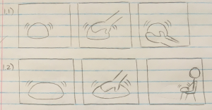
Organizing ideas for storyboarding. (Is this how storyboarding works at all?)

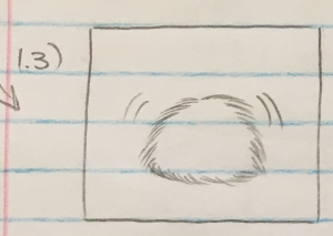
After considering several possibilities for the size and shape, I decided that as a first pass, I would make a palm-sized vaguely-round robot, as it would easily allow for quick and simple interaction with humans – petting, picking it up, etc.

Because I had the idea of a therapy-bot in mind, I think it would also be interesting to explore a lap-sized robot, like a small cat or dog. Of course, this would be for a future iteration of the robot, when the more important aspects of the robot (i.e. interaction, electronic parts) have been developed out.

Some ideas for shape and size, and how a human would interact with it.

One aspect I have yet to decide is whether the robot should have the traditional fur covering, or be left in just its silicone skin. Because it is a palm-sized robot made for picking up and handling, I think both designs are equally valid, and it would come down to personal preference as for which would “feel better” – do you prefer to play with it like a stress ball, or pet it like a small creature? Does the sensation of fur feel more calming, or would a smooth surface be better?

Ultimately, as with everything in this lab – the best solution is to just prototype and test!

Fuzzy or not fuzzy?

In terms of interaction, the robot currently only sits and purrs, regardless of environment and handling. However, in order to have anything worth studying, the robot would definitely need at least one simple degree of interaction (simple mainly for my benefit, to make sure that the hardware design is within my capabilities). We haven’t yet decided on what kind of study we want to do with this robot, but I have been thinking it might be interesting to design a very simple “action-reaction” mechanism into the robot, and see whether, without any instruction at all, humans can be “taught” how to best interact with the robot based solely on the robot’s reactions.

For instance, if the robot clearly gets agitated and trembles excessively when handled roughly (poked roughly, shaken, etc.), how quickly can its human partner realize that 1) the robot is upset, and 2) the robot doesn’t want to be handled roughly? Or if the robot purrs happily when softly petted, or gently picked up, how quickly can the human realize that they can calm down the agitated robot by being nice to it?

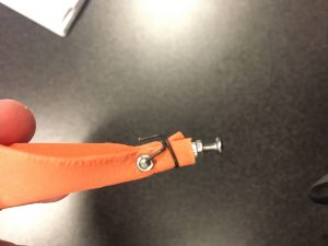
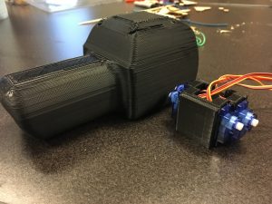
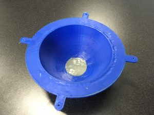
We have decided that the easiest first pass for doing this is to embed an accelerometer into the robot, as a basic measure of “handling roughness”.

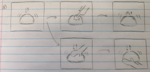
Possible ideas for building basic interactivity into the robot.

At some point during this storyboarding journey, I had a sudden idea: what if we made “Lego” hybrid CuddleBits? Would it ever be possible to make separate DOFs that can be exchanged and mixed almost like the character customization of a video game character?

As much as the ideal appeals to me though, I don’t really think it’s all that feasible, given how completely unrelated our various DOFs have been so far. (That being said, I would still really love for something like this to happen. Someone’s future grad thesis, perhaps?)

BYOCB (build your own CuddleBit)?

Robot Shape
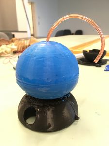
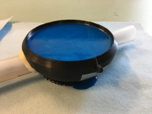
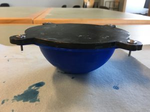
Following the storyboarding exercise, we thought we had enough to work with for my next iteration – making the first full-size prototype.

That being said, in the storyboarding I had only really decided on a size, not a shape –> time to prototype!

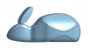
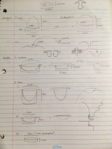
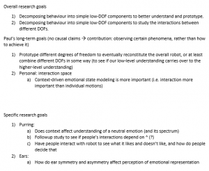
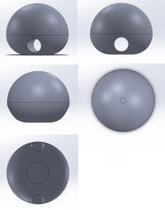
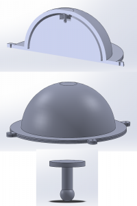
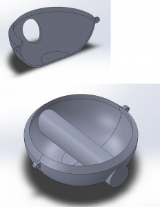
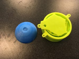
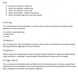
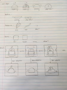
I made a series of small-scale robot shapes – spherical, dewdrop, flattened teardrop – and asked various members of the lab for their opinions.

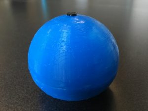
The overwhelming opinion was that spherical is definitely not ideal. Although it is a given that this CuddleBit is probably not going to resemble any existing common creature, taking on the shape of a perfect sphere would make it so unrealistic that people would likely have trouble connecting to it as a pet, or living thing.

Something rather amusing and unexpected occurred during these interviews. Two SPINners immediately gravitated towards the flattened teardrop shape and said “That. But upright.” – essentially like an egg. It was apparently an innate reaction for them that that particular shape was meant to be cradled in their hands in that specific manner. Definitely an interesting notion to keep in mind for designing the robot body.

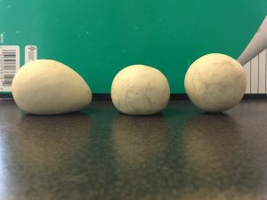
From L to R: Flattened teardrop, dewdrop, sphere.

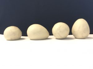
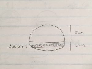
New shape: egg (very left).

Week 7 – Mold design, casting, storyboarding

Week 7 (Feb 26-March 4)
Learning more from the molding process, and some testing on the scaled-down prototype. My first foray into storyboarding.

Mold design
Removed last week’s cast from the mold. Or, rather, attempted to. I appear to have a terrible track record with these things.

Oops…

The resulting silicone piece.

Several issues we noticed during the process:
1) The suction between the mold pieces made it essentially impossible to take them apart. We attempted several solutions, including running the mold under hot water to soften the silicone, using a knife to pry the pieces apart, and trying to twist the top off.
In the end, the only thing that actually worked was breaking the top piece.

Several potential solutions we thought of:
a) Designing the bottom in two pieces instead of 1, and screw them together for the molding process. I thought it might be easier to remove the “outside” of the mold instead of prying the inside out of it.
b) Designing air channels in the mold to make it easier to take the pieces apart (by decreasing the suction).
c) Applying a release agent to the mold pieces before casting. Although this may or may not work as the main problem appeared to be suction rather than stickiness, but it’s worth considering.

2) Button size to dome size ratio. The dome has a built-in depression in the top for a plastic “button” that was going to be used in applying an even downward pressure. This would, theoretically, compress the dome and simulate a breathing motion. After some testing, I have determined that the optimal button size, for the scaled-down test dome at least, is a little larger than the anticipated one, as any smaller would only create a dimple in the top of the dome, and any larger would lead to uneven compression. However, I am unsure how this would scale up – if this button size is a fixed thing, or if it’s a button:dome ratio.

IMG_1034 IMG_1038 IMG_1036
Testing of various different button sizes: small, medium, and large.

3) Air escapes for breathing. There was some initial concern about whether we needed to build separate channels for air to go in/out of the dome when compressing, but after some testing it seems that the hole used for the string to pass through the dome is sufficient for this purpose.

Gluing things to silicone
This was an unexpected problem. It turns out that there is no simple way to attach something to silicone, other than more silicone, or very specialized glue. We had also considered perhaps using hardware (e.g. screws) to attach pieces, but I think that would compromise the intended overall softness/uniformity of the robot body, so I would prefer using additional silicone to glue pieces together when needed (such as when attaching the robot top to the robot body).

Storyboarding
Began some storyboarding for the purring and hybrid CuddleBits, as we had decided that we were probably overdue for trying to nail down some of the design variables. This is my first encounter with storyboarding, so I’m not entirely sure if I’m on the right track with how this works, but it’s been an interesting exercise so far.