Week 10 (March 19-25)
3D modeling and printing the full-size mold. (“3D modeling is hard” may be the understatement of the century.)
Modeling
Apparently I didn’t learn my lesson in high school when I lost an hour of work in AutoCAD because I didn’t save and someone kicked out the power in a row of computers. This time the power stayed on, but SolidWorks crashed and I still hadn’t saved… lesson learned for good this time, I think.
Using the same methods we had decided on while modeling the scaled-down mold, I modeled the positive first (i.e. the actual robot shape), to test how the cast would look, then modeled the cast around it to make sure that all the pieces fit together properly.
I think it’s definitely a good exercise to model the positive first, as I ended up making a few changes to the design. It turned out that with the initial measurements I had chosen, the robot didn’t look as expected (note to self: my hand drawings are most definitely not to scale); in order to steer away from an overly-spherical robot, the bottom of the robot had to be flattened out as much as possible.
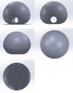
The final body design for the first robot prototype.
As well, I had initially planned to have the motor channel only go partway into the robot body; after some thought, I decided that it would be better for the channel to go through the body, as it would make the motor easier to remove (based on experiences with the first “failed” silicone cast I had made).
Also played around a little bit with the design for this part of the mold. Settled on one that was a little more functionally tricky for casting purposes, but would hopefully work well.
To test that the molds should work as intended, I assembled them in SolidWorks to test that the pieces fit together, and also fit around the positives.
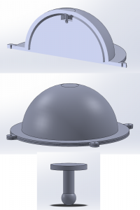
Mold pieces for the top of the robot.
Top image is the assembly – how the pieces would fit together during casting.
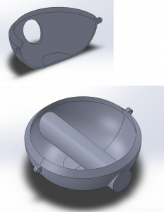
Mold pieces and assembly for the bottom of the robot.
Printing
Ran into some issues while printing the pieces.
The first was that for the first piece we printed (the “outer dome” part for the robot top), we had left out the support structures in an attempt to reduce the amount of material needed for the print – accidentally forgetting that there was a small bit inside the dome that definitely did need a support structure. As a result, the inside top of the dome came out a little messy – some on-the-fly fixing will have to be done before using it in the cast.
As well, due to a misreading of dimensions while modeling, the edges and tabs (used for securing the various pieces together) of the mold were printed with the wrong measurements. To accommodate for that, I made corresponding adjustments on the other half of the mold in order for the two pieces to match.
The second issue was that the cylinder part of the bottom mold had some… problems…
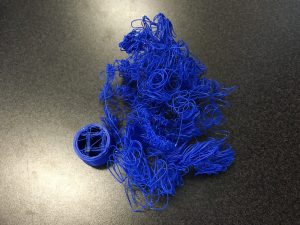
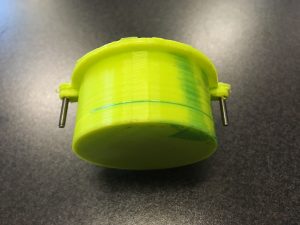
The flying spaghetti cylinder?
No one was in the lab when the error occurred, so we can’t really be sure what went wrong, but some theories are slight z-axis calibration error and nozzle temperature problems. So far, next week’s todo list consists entirely of “fix mold before casting”.