Memo 4

Memorandum 

Date:               February 16th, 2014

To:                  Professor David G. Michelson

From:              EECE 380’s L2D4 Group

Subject:          Weekly Memo for Week 4

This week the software group completed the design of the display and the video filter by using myDAQ; the display has been tested and functions well, however, the video filter still needs additional testing. The hardware group completed the cascaded Common Emitter amplifier and a precision peak detector.

Hardware Sub-group

The goals of the team for the week were

  • Build an amplifier which will be put after the mixer and before the peak detector
  • Build and test a precision peak detector


Cascaded Common Emitter Amplifier


As the previous memo mentioned, an amplifier is needed to make the signal large enough for the peak detector. In this week, we have built a second set of cascaded Common Emitter amplifier in an attempt to have a performant gain. However, it did not function as what we expected. Then we investigated that the DC offset of the cascaded Common Emitter amplifier could give us a high enough output, related to the amplitude of the signal. Therefore, the amplifier will work well if we find the relationship between its output and the amplitude of the input signal.


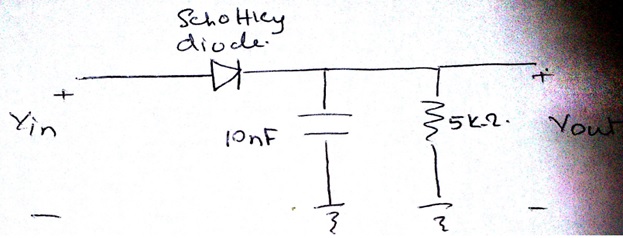
Precision Peak Detector


This week we built a precision peak detector by using the high frequency op amps we received in order to enhance the accuracy. However, it does not function well at around 10MHz. Next week, we will make adjustments on the precision peak detector to solve this problem.
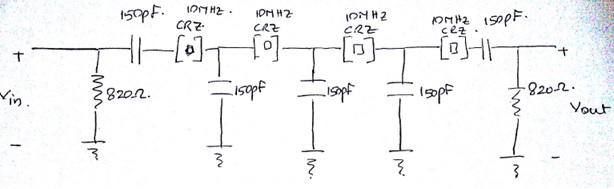
 

Video Filter


This week we built a simple RC circuit which is a low pass filter. After testing, we observed that it does not function accurately as a video filter when the signal is small. To meet our requirements, we decide to complete the video filter by using myDAQ.


The goals of hardware sub-group for this week are all achieved. Additional testing on the precision peak detector will be done. In addition, we are going to combine all parts of the project and perform testing in the next week.


Software Sub-group


The goals of the team for the week were

  • Complete the display for the spectrum analyzer and perform testing.
  • Complete the video filter


Display


In this week, we complete the display for the spectrum analyzer. Our display was having a problem of resetting in last week. To solve this problem we create a design block to set a range for the display and connect it to the reset port of the design block build XY graph. After testing we find out that this method solve the problem efficiently. In addition, we observed that the lowest readable signal of myDAQ is around 0.1V.


Video Filter


The video filter is completed by using a design block Butterworth filter and setting it to be a low pass filter. The high cut-off frequency we choose is 1.1MHZ. Testing of the video filter will be performed in the next week.


Logarithmic Amplifier


In this week, we have figured out how to build logarithmic amplifier by using the LabView. However, to complete this part, data collection and calculations of the relationship between DC voltage and power in dBm is needed. This task will be done in the next week.


The goals of software sub-group for this week are all achieved. We will complete the logarithmic amplifier, perform testing, and combine all parts of the project in the next week.

Weekly Memorandum 2

Memorandum 

Date:               February 2nd, 2014

To:                   Professor David G. Michelson

From:              EECE 380’s L2D4 Group

Subject:          Weekly Memo for Week 2

This week our group divided into two specialised sub-groups – Hardware and Software. The Hardware sub-group consisting of three members would work on building the peak detector, Resolution Bandwidth Filter, Video filter and the Logarithmic Amplifier. The Software sub-group consisting of two members would work on the myDAQ to build the ramp generator and displaying the results on the screen.

Hardware Sub-group

The goals of the team for the week were

  • Finish the Resolution Bandwidth Filter
  • Build a simple Peak Detector.

Resolution Bandwidth Filter

We were asked to utilize the crystals provided to us to build a Crystal Ladder Band Pass filter. Our group decided to build a four Pole Crystal Ladder Band Pass filter. We did a lot of reading on it and decided to create the following design for our purposes.

This design gave us a very nice band pass filter that was centered at 9.997620 MHz with a Band Width of 900Hz. After changing the capacitor values a little bit, we noticed that to have a flatter top, we need to have all the capacitors of the same value. We also learned that the higher capacitance used would give us a narrower band width but there would be a trade-off with the amount of power it would consume instead. This design we thought gave the optimum amount of Bandwidth while we lost about 10dbm of power. This is acceptable since when we put everything together, we will have amplifiers to retain the power of the signal.

Peak Detector

The Peak detector we agreed was the most vulnerable part of our circuit and also the part at which a lot of power would be lost. We first built a simple peak detector which had a design that looked similar to the following.

The time constant was chosen so that it would take 1/10th of the frequency of the input signal. This would make sure that the capacitor does not discharge completely resulting in the DC output of the peak. When we tested the circuit we were getting a great DC offset from the signal generator. To get rid of the offset, we connected a 100Ω resistor in parallel with the above circuit to get rid of the DC waves. After that our Peak detector worked fine except that 0.4V were lost at the output due to the Schottky Diode. We realised that we would need an amplifier to rectify this loss. However, we also learned that normal Op-amps do not operate at high frequencies as high as 10MHz. So we placed an order for high frequency Op-Amp which should arrive later this week. We will then build a precision Peak Detector which will be better for our project.

Thus we finished both our goals for this week in the hardware section.

Software Sub-group

The goal of the software team for the past week was to build a ramp generator.

Ramp Generator

From Tutorial, our group had noted that the local oscillator needed to generate a frequency band between 60Mhz and 64Mhz for our project. This meant that our ramp would have to be between 3.75V and 5.5V from the linear nature of the Local Oscillator. We first introduced ourselves with the various functions of myDAQ and the features we were required to know. After a couple of sessions with the software, we were successful in creating a saw tooth function in the region that we wanted and we even tested the output with the Local Oscillator. We will now concentrate on the displaying the results part of our project requirement.

Those were our tem updates from this week. As mentioned above, we have cleared a lot of ground in terms of fulfilling project requirements. We are now looking to finish the software and the hardware part by the end of next week so that we can all work on putting all the parts together and debug the system as a whole. Rest assured, we are on good track at the moment.