Introduction
This submission is for assignment 1:3 part 1: definitions. It can be summarized by the following 5 key aspects:
- Term: hydropneumatic suspension.
- Audience: mechanical engineering students who only has knowledge about simple components like springs.
- Reading situation: students are assigned this pre-reading material before a lecture about hydropneumatic machinery.
- Criteria: all 3 definitions are appropriate in depth of details, and suitable for the intended audience; the expanded definition has to use at least 4 expansion methods; and the chosen format for references is MLA 9th edition.
- Objective: Practice explaining a technical term accurately and concisely to an audience with little relevant knowledge, in order to recognize the importance of technical writing in professional communications.
Definitions
Parenthetical Definition
Modern vehicles today … The Piranha III armored fighting vehicle, for example, employs the hydropneumatic suspension system (using air and water pressures to manage wheel movements) for superior ride quality on a variety of terrains.
Sentence Definition
Hydropneumatic suspension is a mechanical system designed to utilize the compression properties of gasses and liquids to provide vehicle wheels with optimized movements. With the efficient design, vehicles equipping this type of suspension systems can have enhanced mobility on a variety of terrains.
Expanded Definition
Hydropneumatic suspension is a mechanical system designed to utilize the compression properties of gasses and liquids to provide vehicle wheels with optimized movements. With the efficient design, vehicles equipping this type of suspension systems can have enhanced mobility on a variety of terrains. The word “hydropneumatic” is a shortened combination of two words “hydraulic” and “pneumatic”, which mean “operated by a liquid” and “operated by air” respectively.
Hydropneumatic suspension systems are often used in wheeled vehicles, including but not limited to: luxury convertibles, sedans, trucks and modern tanks. In consumer or commercial automobiles, implementation of hydropneumatic suspension is aimed at facilitating better braking, steering, acceleration and comfort. In armored vehicles, they are used for adaptability on difficult surfaces, assistance for higher firing accuracy and easement of riding.
 Fig. 1. Irish Army Piranha IIIH MRV
Source: “Mowag Piranha.”. Wikipedia. 2023.
Compared to traditional spring suspensions, hydropneumatic suspension avoids usage of large metal springs for force transfer. Because of that, hydropneumatic suspension rids the vehicle of undesirable oscillations of springs, providing smoother drives. Also, since liquids are highly sensitive to changes of pressure, hydropneumatic suspension reacts faster than spring suspensions. However, it does have disadvantages: its manufacture requires more sophisticated equipment, and thus is more expensive.
A typical hydropneumatic suspension system consists of two main parts, as shown in Fig. 2.
- The first part is a spherical container separated into two chambers by a flexible membrane. The upper chamber is filled with a compressible gas, while the lower chamber is filled with hydraulic fluid. The piston at the downward opening of the sphere transfers forces from below, and those forces will be balanced off by liquid pressure delivered through the pump on the right. The pump is used to pressurize the hydraulic fluid. Due to the multiplication effect (the liquid force on a smaller area is the a multiple of that on a larger area) proved by Pascal’s law (The Editors of Encyclopedia Britannica), only a small liquid pressure from the pump is needed to counteract incoming forces.
- The second part is a suspension arm bridging a pivot on the hull and the road wheel. This part connects the motions of those two components, while converting their relative movements into forces for the container part.
By examining Fig. 3, readers can have a closer view of the suspension arm part, and a better understanding of the functionality of such a system.
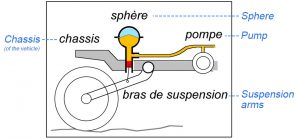
Fig. 2. Diagram of a simple hydropneumatic suspension
Source: “Hydropneumatic Suspension.”. Wikipedia. 2023.
a. Note: This figure is annotated with English translation of names of parts in
blue color, and with dashed lines connecting each to its French counterpart.
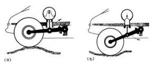
Fig. 3. Comparison of the suspension arm’s two states
Source: Campbell, Colin. “Hydropneumatic Suspension.”. 1981.
a. Note: In this figure, (a) is a state where the wheel is lifted by a bump, while
(b) is where the wheel is lowered by a dent.
Works Cited
Campbell, Colin. “Hydropneumatic Suspension.” Automobile Suspensions, Springer US, 1981, pp. 143–64, http://dx.doi.org/10.1007/978-1-4613-3389-0_9. Accessed 7 Feb. 2023.
“Hydropneumatic Suspension.” Wikipedia, 13 Jan. 2023, https://en.wikipedia.org/wiki/Hydropneumatic_suspension#Basic_mechanical_layout. Accessed 6 Feb. 2023.
“Mowag Piranha.” Wikipedia, 19 Jan. 2023, https://en.wikipedia.org/wiki/Mowag_Piranha. Accessed 6 Feb. 2023.
The Editors of Encyclopedia Britannica. “Pascal’s Principle.” Encyclopedia Britannica, 20 July 1998, https://www.britannica.com/science/Pascals-principle. Accessed 12 Feb. 2023.
Leave a Reply