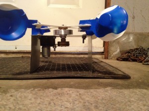
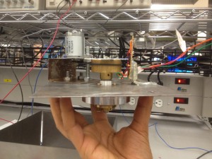
The team spent the week combining the various components of the spectrum analyzer and integrating the hardware and software sub components. The members working in the respective teams helped in the integration process. The team was also involved in calibrating the components that were integrated and functional, further different parts of the report were assigned to team members based on their responsibilities.
Hardware:
The hardware sub-team was heavily involved with understanding UltiBoard and designing a PCB to hold our switch IC. This involved becoming conversant with the software and understanding industry standards for amount of copper, drill sizes etc. The hardware sub team completed a design for the PCB and combined it with 3 other teams to take advantage of the flat price offered by CCI. However due to the long turn around time, the team agreed to use the back up PCB provided by the teaching staff and soldered and tested the switch IC. A major challenge in this process was to solder the chip with the solder iron in the lab, it required a lot of patience and de-soldering.
The hardware team also realized an issue caused by the 8Mhz crystals. The low center frequency of these crystals meant that 104 MHz and 88 MHz, both within our range, are 8 MHz away from 96 MHz which is also in our range therefore we don’t know which of these frequencies gives us the 8 MHz difference. This was corrected by using crystals with higher center frequency i.e. 18Mhz that made sure that 2 frequencies did not give us the same difference in our range. The new crystals were an efficient fix for what could have been a very difficult issue to debug in LabView.
Software:
The software team continued to better the user interface that was created last week. The markers and traces that were implemented last week were debugged and new controls such as center frequency and span as well as start stop frequency were also implemented. The sub team also debugged and troubleshooted the inputs and outputs from the DAQ and programmed the remaining analog input to control a mux to control the switch. Further, the sub team implemented added functionality that was deemed necessary. The frequency modulation index calculation was implemented via Carson’s rule and testing of the software with input from the hardware was also started. The team has also automated one of the markers to find the peak and display it, the team will continue to make efforts to completely mimic the lab machines but the integration and testing of the components is more important at this point.

