Memorandum #10

EECE 380 Design Studio III

Memorandum #10

March 31, 2014

To: Dr. David Michelson

From: Danny Kim, team leader

This memorandum serves as an update for progress of the EECE 380 Design Studio III team, L2C4, during the week of March 24 – 31, 2014.

Hardware Updates:

For our power management system, we will be using three sets of solar panels in series that are capable of producing 20 V and 200mA. When we tested the solar panels on a sunny day, three panels together were outputting around 180mA and 19V even though they were not set up to be most efficiently.  When we hooked up the solar panels to our power management system circuit, the battery was charging according to our expectations.

With the battery alone, we were able to power the Q4000 on standby mode but we have not yet tested the battery when Q4000 would send a message to the satellite to see the current it draws.

This week we were successfully able to implement both our electrical temperature sensor and our wind turbine, which is our electromechanical sensor. We are still currently working on the implementation of the Arduino code for the accelerometer. We will send these three sensors, as well as the current voltage of the battery into the Q4000 through a multiplexer, since there are only two analog inputs. Voltages from each of these inputs will be read periodically by the microcontroller, and then an average value over approximately 10-15 cycles will be calculated and sent to the server via email. We expect to send updated data at least once per minute, if the microcontroller can handle this traffic. We have yet to test the integration of the sensors with the Q4000.

We were also successfully able to complete the flotation structure for the ocean buoy.

Software Updates:

The Embedded C code is able to interface six analog inputs through a multiplexer. The digital outputs from the Q4000 are used for the selector pins of the mux. We switch between mux pairings at each timer event. The email bodies contain all sensor data in specific JSON format to be parsed by the web server.

The web server now writes to a web page that is viewable on all devices on the same LAN. The URL was set up to be localhost:8888/view/surfingconditions, which can be accessed when the Python server is running. This web page displays the most recent surfing condition data, rather than long term data, since our target audience, surfers, would not need to know the surfing conditions from last week, or even two days ago.
Memorandum #9

EECE 380 Design Studio III

Memorandum #8

March 23, 2014

To: Dr. David Michelson

From: Jacklyn Dang, team leader

This memorandum serves as an update for progress of the EECE 380 Design Studio III team, L2C4, during the week of March 17 – 23, 2014.

A high level design of the system was determined this week. We planned to follow the third option in our previous memo, “off-shore surf forecasting system.” This system will involve wind, temperature and wave condition sensors that will be sent through an analog multiplexer into the Q4000 microcontroller. The Q4000 will be programmed to periodically switch between each input of the multiplexer to read each sensor’s data, subsequently transmitting the data via email after a given amount of time cycles. The email will then be received by the ECE server where a local web server will parse the data and display it in a web page for surfers to view.

Hardware Updates:

For our power management system, we will be using three sets of solar panels in series that are capable of producing 20 V and 200mA. This will be used to charge a battery that will power our sensors. We will be using two electrical sensors (temperature meter and accelerometer) and one electromechanical sensor (wind turbine). We will send these three sensors, as well as the current voltage of the battery into the Q4000 through a multiplexer, since there are only two analog inputs. Voltages from each of these inputs will be read periodically by the microcontroller, and then an average value over approximately 10-15 cycles will be calculated and sent to the server via email. We expect to send updated data at least once per minute, if the microcontroller can handle this traffic.

Software Updates:

The embedded C code for the Q4000 is currently programmed to receive a single analog voltage, store on the FFS in a *.dat file, and then later read from it. The timer has been set up to periodically transmit an email containing the data along with a time stamp. We successfully forwarded the data in the body of an email from Gmail to our ECE webmail account within the “.orb” folder. After running “myscript.sh”, we were able to retrieve the email body and store it into a text file locally.

Our software design will involve having a Python web server running on the host PC to periodically run the shell script to retrieve data from the body of incoming emails. All data will be transmitted in JSON format for efficient parsing from both ends of our communication process. The Python server will parse the incoming JSON that contains a time-stamp and reading for the appropriate sensors, which will be displayed on a web page, hosted by this server.


Memorandum #8

EECE 380 Design Studio III

Memorandum #8

March 18, 2014

To: Dr. David Michelson

From: Doug Mosher, team leader

This memorandum serves as an update for progress of the EECE 380 Design Studio III team, L2C4, during the week of March 10 – 17, 2014.

For software, we modified DemoAppsGSM file in order to send a message via satellite to our shared email account. We ended up getting emails but we still need to change the time interval between emails as we were not getting them constantly. Additionally, we we able to print voltage values read from the ADC on the Q4000.

We also discussed some preliminary ideas for the satellite-based oceanography SCADA system. Among our ideas include the following:

Idea #1: Oceanography monitoring system to determine effect of global warming

Argo is a system designed to observe temperature, salinity and currents in the Earth’s oceans. One idea that we discussed was to design somewhat of an extension to the Argo system; that is, a satellite-based oceanographic system that can determine the long-term effects of global warming on oceans by acquiring data on ocean surface temperature, acidity and surface wave velocities. The system will be attached to an ocean buoy. In addition, the system will be sustainable – it will rely on tidal power as a source of energy. Alternatively, we also discussed the possibility of using rechargeable batteries to power the system.

Idea #2: Prohibited motor detection

This system is designed to detect the usage of a motor in areas where motor usage is restricted or prohibited. Using a microphone or a hydrophone, if the sensor is placed in the water, we will be able to detect the presence of a motor. This system would be placed at common entry points and would send a signal whenever a motor is present. This system would be powered by wind power or possibly solar depending on its location.

Idea #3: Off-shore surf forecasting system

Optimal surfing conditions are determined by a number of factors, namely wave speed, ocean swells and water temperature. This ocean buoy system would determine off-shore surfing conditions by measuring temperature, wind speed and wave height. The wind speed at the surface of the ocean mainly determines the wave speed, whereas the wave height is a good indicator of the size of the ocean swell. This system would be powered by batteries that can be charged with wind power.


Memorandum #7

March 10, 2014

To: Dr. David Michelson

From: Lauren Aliman, team leader

This memorandum serves as an update for progress of the EECE 380 Design Studio III team, L2C4, during the week of March 2 – March 9, 2014. This week was primarily spent on final calibrations and preparation for the project presentation.

On Monday, March 3, we held our weekly meeting to prepare the slides for the project presentation. We carefully reviewed notes from the Spectrum Analyzer briefing lecture to ensure that we met all the general requirements. As well, we discussed important outcomes of the project, including CEAB graduate attributes that we applied whilst working on the spectrum analyzer.

On Thursday, March 11, we had our project presentation during the lab session. Before the demo, we divided up the slides so that each team member has an opportunity to present. During the presentation, we received a few minor criticisms from Prof. Michelson regarding some ambiguities in our slides. Other than that, the presentation went smoothly and the finished spectrum analyzer successfully received and displayed an FM signal in the given frequency and power ranges.

In the next weekly meeting, we will discuss new goals for the next project.


Memorandum #5

February 23, 2014

To: Dr. David Michelson

From: Danny Kim, L2C4 Team Leader

This memorandum serves as an update for progress of the EECE 380 Design Studio III team, L2C4, during the week of February 17 – February 23, 2014.

We had our weekly team meeting on Monday, February 17, where we talked about our progress in the software and hardware portions of the project from the previous week.

Updates on Hardware Portion:

The 4 pole crystal ladder filter we previously designed did not have enough gain from its resolution  peak from the noise of the circuit as we hoped. We decided to improve our design by building a 2 pole crystal ladder filter with a better gain. With our original filter having ~1 KHz bandwidth, our new filter has a bandwidth of ~2 KHz in order for us to see how high the peak of a signal is. Previously, the signal was getting attenuated but as a result of our improved crystal ladder filter, at our centre frequency, we are getting a gain of ~10 dBm when the Mixer, Voltage Controlled Oscillator, and RF Amplifier are all connected.

We were having trouble with the output of the crystal ladder filter being too low of a voltage to be accurately measured by the peak detector. We decided to add an amplifier after the filter and before the detector. We designed two different solutions. The first is a CE-CB cascode amplifier that creates isolation from the input to the output and the second is a 4th order butterworth low pass filter using 2 high speed amplifiers. The butterworth was able to pass a signal through with much less distortion and we were able to create a voltage gain of up to 100V/V. We are unsure of which one to use as of now. The butterworth is a much better amplifier, but it comes with the cost of a much more complex circuit.

We spent this week solely on hardware, so there is no update from software portion this week.

In the following week, we plan on meeting on February 24th to discuss current state of the project and plan our goals.


Memorandum #6

February 23, 2014

To: Dr. David Michelson

From: Ryan Wong, team leader

This memorandum serves as an update for progress of the EECE 380 Design Studio III team, L2C4, during the week of February 24 – March 3, 2014.

This weed, we focused mostly on integrating the hardware component with the software component.

Updates on Hardware Portion:

There was much progress on the hardware, finally completing a design for an amplifier that worked at high frequencies. The team constructed a series of three LM7171 inverting amplifiers with an overall gain of 45 dBm. Our implementation of the subsystem block diagrams from the output of the mixer  involved the 10.7MHz BPF, Crystal Filter, cascaded op-amps, peak detector, active LPF, and voltage divider. From there, our filtered DC signal entered into the myDAQ cleanly.


Updates on Software Portion:

This week, we focused mostly on adding extra features to the software portion, as well as integrating it with the hardware component. We played around with the ramp generator to determine the optimal range of frequencies that would produce the more accurate signal, which we decided was between 0.1 to 0.5 Hz. Any frequencies above 0.5 Hz generated a very wide signal that was significantly shifted to the right. We also implemented a means for the user to enter the desired center frequency and the span from the front panel, by using a numeric control and a dial. From these values we were able to determine upper and lower frequencies that we plugged into the X Span and Y Span property nodes of the XY Graph to enable the user to zoom in and out of the graph. We also implemented an algorithm that resets the XY graph after every cycle of the ramp generator. This way, the VI would no longer have buffer issues.

Thus far, the software portion has the following capabilities:

  • Determine  the maximum signal power and store it in a shift register, while continuously comparing the maximum value with the current measured power values. Display the maximum signal on the front panel and reset after every ramp cycle.
  • Determine the corresponding frequency of the signal detected, store it in a shift register and display on the front panel. Reset after every ramp cycle.
  • Count the number of significant signals in one ramp cycle and use this number to determine the modulation index up to 1.5.

We are currently in the process of calibrating the dBm measurements on LabView.

Memorandum #4

February 16, 2014


To: Dr. David Michelson


From: Jacklyn Dang, L2C4 Team Leader


This memorandum serves as an update for progress of the EECE 380 Design Studio III team, L2C4, during the week of February 10 – February 16, 2014.


We had our weekly team meeting on Tuesday, February 11, where we talked about our progress in the software and hardware portions of the project from the previous week. At the conclusion of the meeting, we decided on the goals to be attained by the end of the week.


Updates on Hardware Portion:

 Last week, we had placed an order for some high frequency op-amps to provide gain in the peak detector, and output signal of the mixer. We hoped that using an LM7171 200MHz op-amp would allow us to reach the needed gain at 10MHz, however we were unable to successfully build a non-inverting amplifier. It appeared that even a simple buffer would not work with this IC, outputting a DC voltage that correlated with the supply voltage of the op-amp. This failure led us to designing common-emitter BJT amplifiers instead. These designs have carried out into the subsequent week, as we are still working on obtaining a high gain with poles at the appropriate frequencies.


Updates on Software Portion:

As mentioned in the previous memo, we had completed the software portion of the project, but had not been able to test it without the completion of the hardware portion. During the first lab section this week, we worked on adding both required and extra features to the software portion of the project. We focused on implementing a user friendly and interactive interface for the analyzer that had the ability to zoom in and out on specific areas. We also aimed to add a marking feature to our spectrum analyzer. We were successfully able to implement and test the zoom feature, as well as implement a marker. We have been unable to test the marker due to a problem with LabView that will be described below.


During the second lab session we encountered a problem with the LabView program. The program itself seemed to be lagging quite significantly and therefore it majorly affected the updating of values from the MyDAQ to the graph in LabView and we would not get a continuous, fast updating view of our signal. We know that this is not caused by our sample number or sample rate in the MyDAQ assistant as we had previously used the same values and not had any problems, but we also experimented by increasing samples and sample rate which still produced the lagging output. We have consulted with the TA and with the lab technician that was available during the lab, but neither had any insight into the problem. We believe that the computer we were on was just running slowly that day, and that the next time we run LabView  the program will run smoother. If not our task for next week will be finding a solution to this current problem.

We plan on meeting during the reading week to continue working on the hardware portion of the project. Our next scheduled meeting will be on Monday February 24th.

Memorandum #3

February 10, 2014

To: Dr. David Michelson

From: Lauren Aliman, L2C4 Team Leader

This memorandum serves as an update for progress of the EECE 380 Design Studio III team, L2C4, during the week of February 3 – February 9, 2014.

We had our weekly team meeting on Monday, February 3, where we talked about our progress in the software and hardware portions of the project from the previous week. We also talked about how each individual component of the Spectrum Analyzer works and how they all tie together. At the conclusion of the meeting, we decided on the following goals to be attained by the end of the week:

Hardware

  • Develop “unit” tests for each separate block
  • Simulate the entire system for integration testing of the RBW and peak detector, replacing the MyDAQ visual display block with the lab spectrum analyzer

Software

  • Attain a good understanding of the theory behind the software design.
  • Generate an XY-graph that acquires data from the ramp generator (y-axis) and from an analog myDAQ input (x-axis).

Updates on Hardware Portion:

Last week’s issue regarding unexpected gain at high frequencies outside of the RBW filter was solved by adding the 10.7MHz BPF in series with the RBW. It was noticed that placing this BPF at the input the crystal ladder had different effects than placing it at the output. We attempted to use the RF amplifier that was provided in our kit to add gain to our ~10MHz filtered signal, however the amplifier provided gain for frequencies that we considered noise, so the professional 10.7MHz BPF was connected after the RF amplifier to eliminate these high frequencies.

The current peak detector will be upgraded to have an op-amp to compensate for the diode voltage drop. However, the 10MHz op-amp that we purchased had major attenuation starting just below 1MHz, to the point where there was an unreadable signal at 10MHz. A proposed solution was to use a 100MHz op-amp that causes no attenuation at 10MHz. This part has been ordered and we will attempt to have a functional precision peak detector by the start of next week.

Updates on Software Portion:

During the first lab session, we spent some time talking about how the outputs from each component of the project look like, in both the time and frequency domains. By doing so, we were able to get a clear picture of what was going on, which made designing the software portion a lot more straightforward.

To display the amplitude of a signal in the y-axis of the graph, we connected a DC signal from a signal generator to one of the analog inputs in myDAQ which we then mathematically manipulated to display the corresponding power in dBm. For the x-axis, we adjusted the ramp generator to have voltages ranging from 3V to 6V. We then came up with a linear function, that simulates the behavior of a local oscillator, to convert the ramp generated voltages to corresponding frequencies between 45 MHz and 57 MHz. By the end of the second lab session, we ended up with a graph consisting of a single pulse that sweeps across the displayed frequency range (45-57 MHz). This output makes sense because we were only feeding the myDAQ input with a constant DC signal. On the other hand, the output from the peak detector would have to be a DC signal whose voltage changes along with the signal from the local oscillator; in other words, each frequency in the given range corresponds to a different output voltage from the peak detector. In theory, the display should work; however, we are yet to come up with a method to test the software portion without connecting it to the peak detector.

We will have our next weekly meeting on Tuesday, at the start of the lab session, to plan out this week’s goals.

Memorandum #2

February 2, 2014

To: Dr. David Michelson

From: Douglas Mosher, L2C4 Team Leader

This memorandum serves as an update for progress of the EECE 380 Design Studio III team, L2C4, during the week of January 28 – February 2, 2014.

On Monday, January 27, our team held a meeting, where we delegated responsibilities for the spectrum analyzer project. The team was broken down as follows: Jackie and Lauren will be responsible for the software portion (MyDAQ, LabView, LO, ramp generator, etc.) and Doug, Danny and Ryan will be responsible for designing the hardware (peak detector, crystal ladder, filters, etc.).

The software team focused on becoming familiar with LabView. During the second lab period ,a successful ramp generator was implemented and adapted to work with the MyDAQ module. We implemented the ramp generator by building a block diagram in LabView. We attached a signal simulator to the MyDAQ output and then enclosed the system with a while loop. Our team encountered a problem where the ramp generator would periodically stop and then begin running again. This was resolved by changing the settings in LabView to continuously output samples from the signal simulator. We were also successfully able to output the ramp generator through the MyDAQ and were able to verify the output using an oscilloscope. We also spent time to fully understand the theory behind the the software design.

The hardware team focused on the peak detector and the crystal ladder this week. 10MHz and 11MHz op-amps were ordered on Friday, January 31, to be used for a precision peak detector. Our team, as well as several others in our lab section, encountered an issue where the AC signal from the RF generator had a significant offset in its amplitude when connected to a basic peak detector. This issue was solved by adding a first-order high pass filter (RC circuit) before the input of the basic peak detector. The current design requires improvement, as the detected peak has a slight voltage drop compared to the actual AC signal’s peak. This should be fixed with a precision peak detector design.

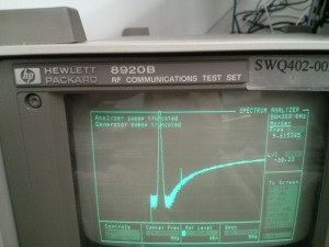
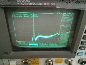
As for the crystal ladder circuit, we managed to generate a BPF with a BW of ~1kHz. However, due to the faultiness in the crystals, the center frequency is slightly off from 10MHz (~9.9987MHz). Another issue was that the BPF would negate all frequencies relatively close to 10MHz, however, higher frequencies in the 50-54MHz range were not stopped. After observing the spectrum across a 100MHz range, we noticed that the dBm gradually increased to values higher than the amplitude of the BPF itself (Figure 1). Filtering the input of the crystal ladder improved this issue (Figure 2).

Figure 1: BPF without correction

Figure 2: BPF with correction

We plan to meet after lecture on Monday, February 3 to discuss component testing and subsystem interfacing, as well as plan out new weekly goals.


Memorandum #1

January 26, 2014

To: Dr. David Michelson

From: Ryan Wong, L2C4 Team Leader

This memorandum serves as an update for progress of the EECE 380 Design Studio III team, L2C4, during the week of January 21-27, 2014.

Before our first lab session, we set up our team blog, created a Facebook group, and organized a Google drive folder for shared documents. We will be using these tools to communicate with each other, as well as to maintain all relevant project files.

Our team met during our two designated lab times on Tuesday and Thursday from 3:30-6:30pm. During the first session, we used signal generators and spectrum analyzers to observe frequency components of waves sent through a splitter and a mixer. The primary focus of these lab activities were to become comfortable with the user settings and controls on the spectrum analyzers. The second lab session focused on using a Voltage Controlled Oscillator (VCO) and an RF Amplifier. By the end of the second lab period, we had connected the VCO and the RF source into the L and R inputs of the Mixer, and sent the output through a 10.7MHz BPF into the spectrum analyzer. The result of this was an important discovery, as we were able to determine the necessary tuning range of the VCO for our custom spectrum analyzer.

In terms of task breakdown and delegation, each team member is currently doing independent research to gain a high level understanding of each component of the spectrum analyzer. We have shared important findings with each other on our Facebook group. We will start to assign more specific tasks at the start of next week.