February 2, 2014
To: Dr. David Michelson
From: Douglas Mosher, L2C4 Team Leader
This memorandum serves as an update for progress of the EECE 380 Design Studio III team, L2C4, during the week of January 28 – February 2, 2014.
On Monday, January 27, our team held a meeting, where we delegated responsibilities for the spectrum analyzer project. The team was broken down as follows: Jackie and Lauren will be responsible for the software portion (MyDAQ, LabView, LO, ramp generator, etc.) and Doug, Danny and Ryan will be responsible for designing the hardware (peak detector, crystal ladder, filters, etc.).
The software team focused on becoming familiar with LabView. During the second lab period ,a successful ramp generator was implemented and adapted to work with the MyDAQ module. We implemented the ramp generator by building a block diagram in LabView. We attached a signal simulator to the MyDAQ output and then enclosed the system with a while loop. Our team encountered a problem where the ramp generator would periodically stop and then begin running again. This was resolved by changing the settings in LabView to continuously output samples from the signal simulator. We were also successfully able to output the ramp generator through the MyDAQ and were able to verify the output using an oscilloscope. We also spent time to fully understand the theory behind the the software design.
The hardware team focused on the peak detector and the crystal ladder this week. 10MHz and 11MHz op-amps were ordered on Friday, January 31, to be used for a precision peak detector. Our team, as well as several others in our lab section, encountered an issue where the AC signal from the RF generator had a significant offset in its amplitude when connected to a basic peak detector. This issue was solved by adding a first-order high pass filter (RC circuit) before the input of the basic peak detector. The current design requires improvement, as the detected peak has a slight voltage drop compared to the actual AC signal’s peak. This should be fixed with a precision peak detector design.
As for the crystal ladder circuit, we managed to generate a BPF with a BW of ~1kHz. However, due to the faultiness in the crystals, the center frequency is slightly off from 10MHz (~9.9987MHz). Another issue was that the BPF would negate all frequencies relatively close to 10MHz, however, higher frequencies in the 50-54MHz range were not stopped. After observing the spectrum across a 100MHz range, we noticed that the dBm gradually increased to values higher than the amplitude of the BPF itself (Figure 1). Filtering the input of the crystal ladder improved this issue (Figure 2).
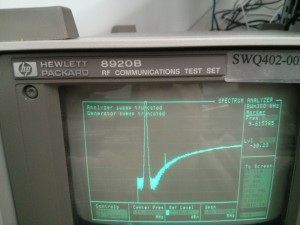
Figure 1: BPF without correction
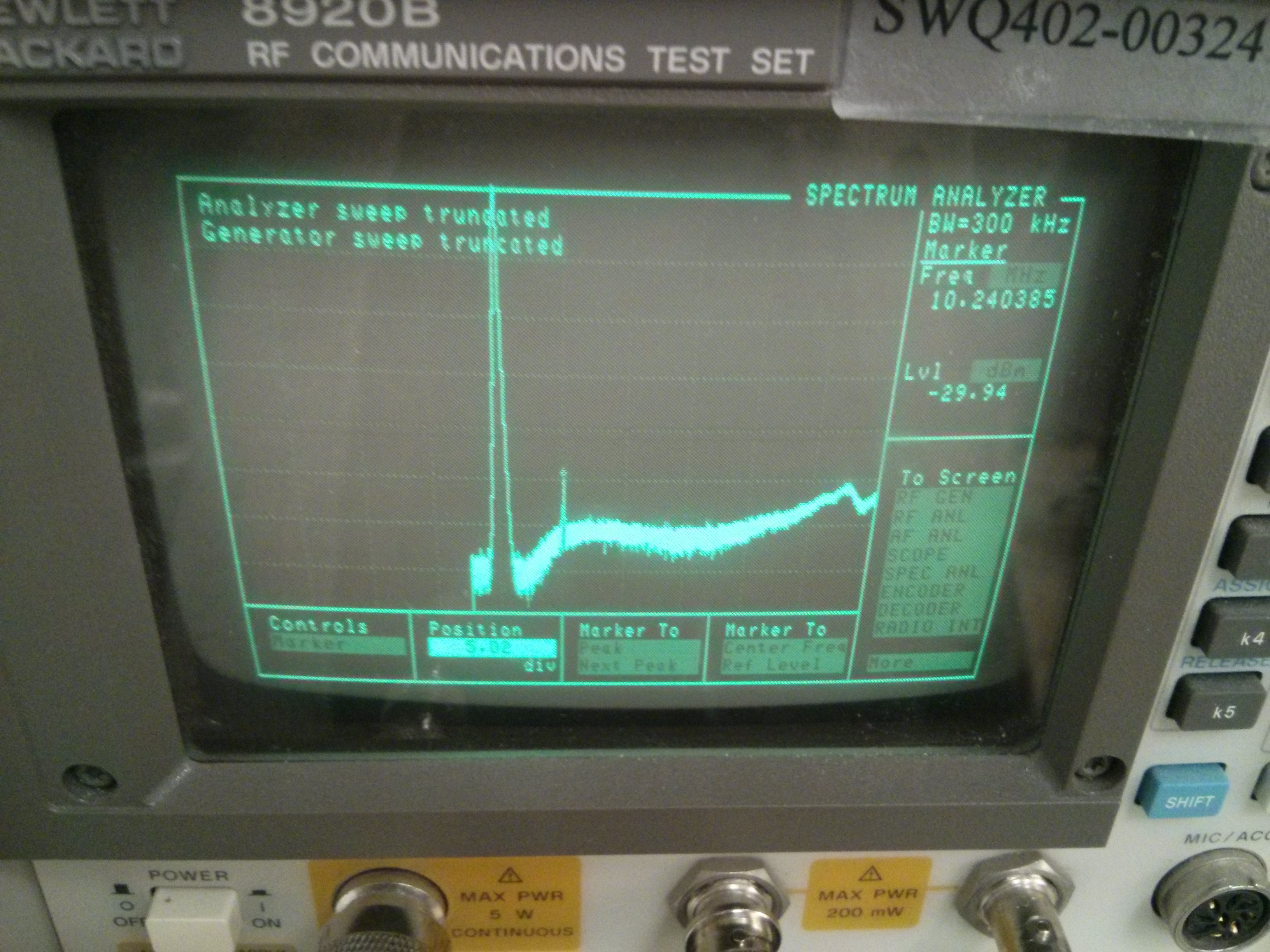
Figure 2: BPF with correction
We plan to meet after lecture on Monday, February 3 to discuss component testing and subsystem interfacing, as well as plan out new weekly goals.