Memorandum #9

EECE 380 Design Studio III

Memorandum #8

March 23, 2014

To: Dr. David Michelson

From: Jacklyn Dang, team leader

This memorandum serves as an update for progress of the EECE 380 Design Studio III team, L2C4, during the week of March 17 – 23, 2014.

A high level design of the system was determined this week. We planned to follow the third option in our previous memo, “off-shore surf forecasting system.” This system will involve wind, temperature and wave condition sensors that will be sent through an analog multiplexer into the Q4000 microcontroller. The Q4000 will be programmed to periodically switch between each input of the multiplexer to read each sensor’s data, subsequently transmitting the data via email after a given amount of time cycles. The email will then be received by the ECE server where a local web server will parse the data and display it in a web page for surfers to view.

Hardware Updates:

For our power management system, we will be using three sets of solar panels in series that are capable of producing 20 V and 200mA. This will be used to charge a battery that will power our sensors. We will be using two electrical sensors (temperature meter and accelerometer) and one electromechanical sensor (wind turbine). We will send these three sensors, as well as the current voltage of the battery into the Q4000 through a multiplexer, since there are only two analog inputs. Voltages from each of these inputs will be read periodically by the microcontroller, and then an average value over approximately 10-15 cycles will be calculated and sent to the server via email. We expect to send updated data at least once per minute, if the microcontroller can handle this traffic.

Software Updates:

The embedded C code for the Q4000 is currently programmed to receive a single analog voltage, store on the FFS in a *.dat file, and then later read from it. The timer has been set up to periodically transmit an email containing the data along with a time stamp. We successfully forwarded the data in the body of an email from Gmail to our ECE webmail account within the “.orb” folder. After running “myscript.sh”, we were able to retrieve the email body and store it into a text file locally.

Our software design will involve having a Python web server running on the host PC to periodically run the shell script to retrieve data from the body of incoming emails. All data will be transmitted in JSON format for efficient parsing from both ends of our communication process. The Python server will parse the incoming JSON that contains a time-stamp and reading for the appropriate sensors, which will be displayed on a web page, hosted by this server.
 

Memorandum #2

February 2, 2014

To: Dr. David Michelson

From: Douglas Mosher, L2C4 Team Leader

This memorandum serves as an update for progress of the EECE 380 Design Studio III team, L2C4, during the week of January 28 – February 2, 2014.

On Monday, January 27, our team held a meeting, where we delegated responsibilities for the spectrum analyzer project. The team was broken down as follows: Jackie and Lauren will be responsible for the software portion (MyDAQ, LabView, LO, ramp generator, etc.) and Doug, Danny and Ryan will be responsible for designing the hardware (peak detector, crystal ladder, filters, etc.).

The software team focused on becoming familiar with LabView. During the second lab period ,a successful ramp generator was implemented and adapted to work with the MyDAQ module. We implemented the ramp generator by building a block diagram in LabView. We attached a signal simulator to the MyDAQ output and then enclosed the system with a while loop. Our team encountered a problem where the ramp generator would periodically stop and then begin running again. This was resolved by changing the settings in LabView to continuously output samples from the signal simulator. We were also successfully able to output the ramp generator through the MyDAQ and were able to verify the output using an oscilloscope. We also spent time to fully understand the theory behind the the software design.

The hardware team focused on the peak detector and the crystal ladder this week. 10MHz and 11MHz op-amps were ordered on Friday, January 31, to be used for a precision peak detector. Our team, as well as several others in our lab section, encountered an issue where the AC signal from the RF generator had a significant offset in its amplitude when connected to a basic peak detector. This issue was solved by adding a first-order high pass filter (RC circuit) before the input of the basic peak detector. The current design requires improvement, as the detected peak has a slight voltage drop compared to the actual AC signal’s peak. This should be fixed with a precision peak detector design.

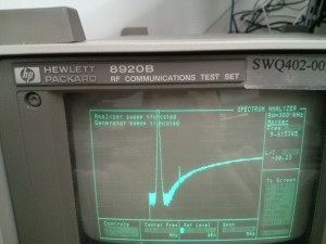
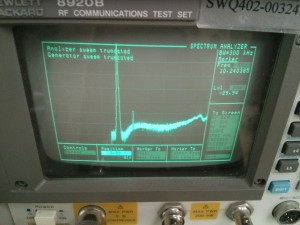
As for the crystal ladder circuit, we managed to generate a BPF with a BW of ~1kHz. However, due to the faultiness in the crystals, the center frequency is slightly off from 10MHz (~9.9987MHz). Another issue was that the BPF would negate all frequencies relatively close to 10MHz, however, higher frequencies in the 50-54MHz range were not stopped. After observing the spectrum across a 100MHz range, we noticed that the dBm gradually increased to values higher than the amplitude of the BPF itself (Figure 1). Filtering the input of the crystal ladder improved this issue (Figure 2).

Figure 1: BPF without correction

Figure 2: BPF with correction

We plan to meet after lecture on Monday, February 3 to discuss component testing and subsystem interfacing, as well as plan out new weekly goals.


Memorandum #1

January 26, 2014

To: Dr. David Michelson

From: Ryan Wong, L2C4 Team Leader

This memorandum serves as an update for progress of the EECE 380 Design Studio III team, L2C4, during the week of January 21-27, 2014.

Before our first lab session, we set up our team blog, created a Facebook group, and organized a Google drive folder for shared documents. We will be using these tools to communicate with each other, as well as to maintain all relevant project files.

Our team met during our two designated lab times on Tuesday and Thursday from 3:30-6:30pm. During the first session, we used signal generators and spectrum analyzers to observe frequency components of waves sent through a splitter and a mixer. The primary focus of these lab activities were to become comfortable with the user settings and controls on the spectrum analyzers. The second lab session focused on using a Voltage Controlled Oscillator (VCO) and an RF Amplifier. By the end of the second lab period, we had connected the VCO and the RF source into the L and R inputs of the Mixer, and sent the output through a 10.7MHz BPF into the spectrum analyzer. The result of this was an important discovery, as we were able to determine the necessary tuning range of the VCO for our custom spectrum analyzer.

In terms of task breakdown and delegation, each team member is currently doing independent research to gain a high level understanding of each component of the spectrum analyzer. We have shared important findings with each other on our Facebook group. We will start to assign more specific tasks at the start of next week.