Q: Why did the circuit go to therapy?

A: Because it had too many unresolved issues and couldn’t find its ground!

Circuit Board

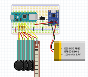
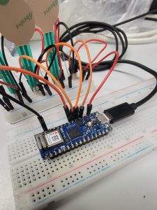
Okay, so the beautiful fritzing diagram I designed last week may not have worked out as well when Dr. Bob and I tried to go off-road a bit to connect the JST connectors to the same board instead of a separate smaller one like we were thinking last week.

Back of circuit board
Front of circuit board

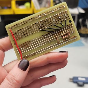
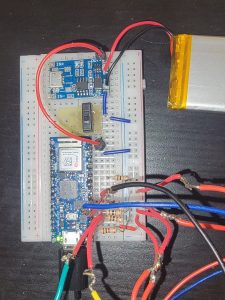
Good news: with some fancy underneath and on-top wiring what we currently have is working perfectly.

Bad news: The TP-4056 Lithium Battery Charger is on hold for another week so we’re still not wireless as ECHO is dependent on being connected to my laptop for power and to send data (both things I’m planning to resolve ASAP).
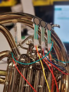
Sensors

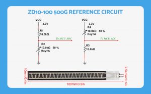
With the female JST connectors on my circuit board, it was time to solder up my flex bend sensor, shorten the wires of my existing FSRs, and attach them all to male JST connectors.  By using JST connectors instead of soldering them directly to the circuit board like in my previous prototypes, this will allow easier and more protective storage/transportation of ECHO, but will also allow me to easily swap out a sensor with a backup if needed.

3D Printing

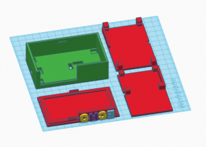
This time around, I’m starting to feel like a pro with the 3D printer (or maybe I just learned to measure twice before I print something). Regardless, with the circuit board around 75% completed, I finally have the measurements I need to begin designing a 3D-printed box that will clip onto my French horn.

Design Considerations:

  • The design should accommodate JST connectors, allowing them to exit the box.
  • The microcontroller’s LED should be visible to easily check its connection status.
  • Include holes for the antenna and a battery On/Off switch.
  • The design should have a slot for the microcontroller to plug in.
  • The device should be compact enough to clip onto a horn without interfering with valve or slide movement.
  • Ensure a secure fit for the Li-Po battery and circuit board to minimize the risk of damage.
  • The circuit board and battery should be easily removable for charging and repair purposes.

Design Solutions Implemented (so far):

  • Designed shelf inserts inside the box with “arms” to securely hold the battery and circuit board in place.
  • The “arms” of the shelf holding the circuit board are designed to fit into specific holes in the box’s floor, preventing any sliding movement.
Latest box and inserts design

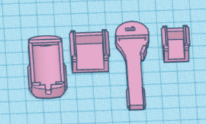
I’ve also started working on an update to my original key clip design which will include a snap-on cover to protect where the electrical wires are soldered to the FSRs after an unfortunate mishap I had this week breaking off the wires of my Li-Po battery.

Latest FSR clip prototype with clip-on cover

Final thoughts

Knock on wood, but by next week I hope to finalize my box design, finish up my circuit board, and edit my arduino code so that it can send data wirelessly to MaxMSP using UDP send/recieve.

Onwards!

Ahhhh, IC what was causing the problem!

Things are really starting to come together quickly, so here’s a quick overview of my progress this past week!

Flex Bend Sensor

Firstly, the flex bend sensor I ordered last week finally arrived. I integrated it into my prototype electronic circuit and updated the Arduino IDE code for testing. Once I solder wires to the sensor pins, my next step will be sewing a channel on a glove to secure it. I plan to sew the channel from the cuff towards the palm to measure the bend of my inner wrist.

IMU Module

Initially, I considered using an accelerometer attached to my wrist to track movement. However, the Arduino Nano 33 IoT comes with a built-in IMU module. Intrigued by its capabilities, I decided to incorporate it into my project. While the flex bend sensor is ideal for measuring the hand’s position in the bell (open, 1/2 stopped, closed), the IMU module offers a unique opportunity to track performance gestures such as bells up, cues, or general movement within the performance space.

To integrate the IMU module, I followed Arduino’s documentation. Although I could read the incoming data from my analog pins without issues, I encountered problems when trying to use analogRead() and IMU.readAcceleration simultaneously. After systematically commenting out sections of my code, I determined that both the analog pins and the IMU module functioned correctly separately. A bit of research led me to discover that the Arduino_LSM6DS3 library uses I2C via pins A4 and A5 to communicate with the IMU module. By simply relocating my flex bend sensor from A4 to A6, everything started working smoothly!

Circuit Board

Additionally, Dr. Bob introduced me to Fritzing, an electronics and

Prototype board that I built using Fritzing

prototyping software. This helped me streamline my previous prototype circuit and devise a solution for integrating the TP-4056 Lithium Battery Charger and Protection Module, along with a switch. This setup allows my microcontroller to operate on a LiPo battery during performances, eliminating the need for a wired power source.

The transformation of my prototype electronic circuit board is remarkable! It’s becoming so much simpler. In fact, it might soon transition from a prototype to a final design. To organize the multiple components and wiring for ECHO’s final version, I plan to use Adafruit’s Perma-Proto 1/2 sized breadboard. Additionally, a smaller breadboard will be positioned underneath to accommodate JST connectors. This setup will enable me to easily attach and detach my sensors for storage and replacement, should any get damaged.

Onwards!

Prototype board from February, using two breadboards and only three sensors
Most up-to-date prototype, on one 1/2 sized breadboard with the addition of 5 sensors, a switch, and a battery charging module

Why did the music technology student team up with the painter?

A: Because they knew they could make an electrifying work together!

During UBC’s Bang! Festival on April 14th, I will be giving a capstone presentation and demonstration at 2pm to showcase how ECHO can be utilized to control various audio/video/lighting processes. In preparation for this event, I reached out to artist Randy McCormick to explore the possibility of collaborating and creating artwork that I could manipulate using Jitter in Max. For one of the pieces, which was painted on glass, I’m also considering experimenting with DMX lighting, mirrors, and projections through the artwork itself.

After numerous phone calls and messages, I’m thrilled to announce that I’ve received the finished works from Randy. Stay tuned for further details as I delve into experimenting with different methods of manipulating these artworks!

Onwards!

Me standing next to artist Randy McCormick holding the two aforementioned works.

Why did the laptop go to the doctor?

A: Because it had a virus and needed a byte of medicine!

In all seriousness though, my laptop is no longer functioning properly and will be sent in for a check-up despite my troubleshooting efforts this week. Consequently, software development had to take a backseat, which wasn’t what I originally planned.

On a brighter note, I’ve made progress in finding a solution for tracking the player’s hand position in the bell! After considering various options such as accelerometers, accelerometer/gyroscope combos, stretch sensors, pressure sensors, or utilizing the built-in sensors of a smartphone or smartwatch, I’ve decided to order a flex sensor.      This type of sensor measures the amount it bends or deflects, making it ideal for detecting the nuanced movements involved in hand-stopping.

I chose the flex sensor because I wanted to pay homage to one of the distinctive aspects of classical horn playing: hand-stopping. Traditionally, hand-stopping was used to play diatonically/chromatically on the natural horn. Therefore, it was crucial to find a sensor capable of capturing the different degrees of hand-stopping. The flex sensor will be positioned on the inner wrist, possibly integrated into a glove of some sort, to accurately measure the bend of the wrist as it transitions from an open to a stopped position.


Onwards!

I’m sensing something… spectacular!

Behold the latest addition: ECHO! The Arduino is finally connected to the sensors which are seamlessly adhered to the key clips and attached to my horn. As such, it’s time to take a bit of a pause on hardware (don’t worry, the accelerometer is still in my near-future plans) and focus on expanding my match patch further to start to include the control things like effects plugins and recording.

Onwards!

Spam prevention powered by Akismet