Vancouver Convention Centre: A Case Study

Part 1: Understanding Urban Water Systems

Why are urban water systems important?

The management of urban water systems is extremely important as water is a valuable resource that is not treated as such. Sustainable urban water system design needs to consider groundwater recharge, evapotranspiration, and runoff; these are all key in using an ecosystem approach to design.

Currently humans impact the water cycle in two main ways: creating impervious ground and polluting water. Maintaining the water cycle key affects a multitude of items such as wildlife and soil conditions, these are only a few of the reasons this topic is essential for engineers to understand.

What water systems are currently in place?

Typically, cities have a potable water system and sewer water system. Newer cities also have a storm water system while older cities have this combined with the sewer system. Many north American cities have storm/sewer water separation projects underway.

Where is there room for improvement?

New developments are often required to have a water management plan to try to mimic the existing water system. Additionally, cities many require a comparison of historical water system to post development conditions. Design techniques that are slowly becoming common practice include a grey water system for non-potable needs.

Water demand has been decreasing in north America in recent years largely due to low flow fixtures. Education regarding water as a resources and water conservation is also key. One of the areas with the largest opportunity to reduce water demand is irrigation. Current irrigation practices include a large amount of run off and new technologies exist to improve this, having new technologies improved and implemented is a large challenge. Building scale treatment is an area that is up and coming; currently technology allows efficiency at the district level which means reduction in pumping stations and piping could soon be a reality.

Part 2: Case Study – Vancouver Convention Centre

The Vancouver Convention Centre underwent extensive construction with the addition of the west building for the 2010 Olympic Winter Games. Almost 9 years later the convention centre is the world first convention centre that is certified double LEED platinum. When it opened, the convention centre was certified LEED platinum for new construction; just last month the building received its second LEED platinum certification for operation and maintenance.

The Vancouver Convention Centre

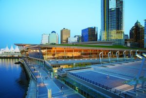
One of the key design features that allows the convention centre to operate to such high standards is the sophisticated black water treatment. The “plant recycles grey and black water that goes back into [the] washrooms for toilet flushing and is used for rooftop irrigation during warmer weather.” Additionally, the convention centre has a “seawater heating and cooling system [that] takes advantage of the adjacent seawater to produce cooling for the building during warmer months and heating in cooler months.”

Compared to a baseline LEED building the convention centre uses 38% less potable water due to the treatment plant and fixture choices. Since construction the treatment plant has increased its capacity by 30%, having a smaller capacity in to start with allowed for changed to be implemented easier. Furthermore, the convention centre has an “Indoor Water Use Reduction Policy” and is actively trying to promote water reduction.

In addition to the water systems the convention centre has many other sustainable features including beehives and a green roof.

Overall seeing the encouraging media reviews about the convention centre is great for the City of Vancouver.

References:

https://www.vancouverconventioncentre.com/

http://www.pcl.com/Projects-that-Inspire/Pages/Featured-Projects/VCC-Sets-LEED-Platinum-Record.aspx

IDP: Use of Virtual Reality

The term virtual reality (VR) can be interpreted in different ways depending on the context. In the building industry it is most commonly used for computer mediated systems, environments, and experiences. In other words it is used to create 3D models of projects that are supposed to aid the design process. VR tools are still Very rarely used in practice, despite the fact that many benefits have already been identified.

Advantages

The combination of VR tools and VR immersive display systems can bring real value to the design review, the communication of the design intent, and it can increase the meeting efficiency. The use of this technology enables users to walk through a 3D model of a given project and by doing so helps to understand the aesthetics of the design because it gives the viewer a more direct feel of depth and volume of the space, which is more difficult by just looking at a static layout.

Furthermore meetings and discussions gain a new level of efficiency, because participants are more engaged and act more professional. The use of VR models brings external people up to speed to the current status easier and faster, leveling the expertise and familiarity with the design between different disciplines. This keeps participants more engaged in issues, that not necessarily regard their own discipline. This provides a holistic and diverse input, which then can spark deep questions and lead to unexpected discoveries, that otherwise might not have been detected until building turnover.

Challenges

This is not to say that VR tools do not pose difficulties or challenges. When using VR the appropriate level of detail has to be considered, as too many trivial issues might arose from a too detailed model. Similarly sometimes less is more when it comes to the modeled environment. Often intermediate designs are filled with placeholders, which will be redesigned in a later state of the process. Are those placeholders to detailed they might convey a wrong image of the design and could create a misinterpretation for those not familiar with the design process.

The preparation of  VR models requires a significant amount of preparation and coordination effort, a process that usually takes up several days. By the time the model is finished the design might have already changed.

Conclusion

To sum up, VR tools give opportunities to improve the design process by increasing meetings efficiency, and helping to keep all participants engaged, so that maybe even hidden issues can be identified. But at the same time very careful planning in preparing is necessary to avoid misinterpretations due to a unfit level of detail in the model. Today Virtual Reality is still underutilized, but one can hope that as the industry develops and becomes better defined the use those tools will increase and improve the design process.

Sources:

“Virtual Reality to Support the Integrated Design Process: A Retrofit case Study”
Yifan Liu, Jennifer Lather, John Messner, 2014

The Dutch View Rising Sea Level as Opportunity, Rather Than Threat

In the Netherlands, a country that largely lies below sea level, an innovative approach to urban storm water management is not just an achievement, but a necessity. The Dutch have a unique view of their situation and choose to “live with the water, rather than struggle to defeat it.” In fact, the special relationship with water develops at a young age for those who grow up in the country, as children are thrown into the pool fully clothed to earn a swimming certificate. The fact that flooding is a major threat to the country is approached head on with a combination of Dutch ingenuity and determination.

Low Impact Design 

The Dutch hold the view that traditional flood barriers and storm water management practices are not adequate to address the rising tides brought on by climate change. Their solution is to let the water in, where possible, rather than continuing to build up and against it.

The Dutch devise lakes, garages, parks and plazas that are a boon to daily life but also double as enormous reservoirs for when the seas and rivers spill over.”

Water Plaza Rotterdam: A community space where people and water coexist
LID mimics the natural water system for collection and drainage of storm water

A keen example of this low impact design for storm water is the Water Plaza in Rotterdam, a public space that has been designed as a community hub but also features sunken infrastructure and green, pervious areas to sustainably collect rain and storm water and provide drainage.

Making Room for the River

The Dutch are using concepts of integrative water management and low impact design to redesign cities and “make room for the river.” Instead of building flood defences higher, the Dutch are actually taking on the task of removing these barriers to provide room for swelling rivers. The benefit of this is two-fold: sustainable flood management combined with generation of urban living space.

The redesigned River Waal provides room for river swells and an island with riverside park

The room for the river concept re-generates the connection between local communities and the natural water ecosystem by developing urban river parks and recreation along the rivers. Banks of the River Waal have been constructed as large gradual slopes, both increasing the floodplain and providing space for water infiltration and communities to gather along the river.

Bringing the Dutch Model to Canada

The province of Alberta, like many other regions worldwide, are excited about what the Dutch are doing to prepare for flooding. In response to the terrible floods in 2014 in Calgary, Alberta, the province has closely collaborated with Dutch water authorities to implement Room for the River integrative water management practices right here at home in Canada!

References:

“How the Dutch Make ‘Room for the River’ by Redesigning Cities.” Scientific American: https://www.scientificamerican.com/article/how-the-dutch-make-room-for-the-river/

“The Dutch Have Solutions to Rising Seas. The World is Watching.” The New York Times: https://www.nytimes.com/interactive/2017/06/15/world/europe/climate-change-rotterdam.html?_r=0

Ruimte voor de rivier website: https://www.ruimtevoorderivier.nl/english/

Alberta’s Room for the River Approach: https://albertawater.com/how-is-water-governed/what-is-room-for-the-river

Water Plaza Rotterdam: http://www.publicspace.org/en/works/h034-water-square

Images 1 & 2

Image 3

Image 4

Constructed Wetlands I

One of the alternative solutions to wastewater treatments that are widely used nowadays are the constructed wetlands. These wetlands are shallow pools developed specifically for storm or waste water treatment that create growing conditions suitable for wetland plants. They are great alternatives to remove contaminants from wastewater, and have been used for decades now.
Constructed wetlands have the same properties as natural wetlands, and are designed to provide water quality benefits through various process that will ultimately minimize pollution prior to the water entry to streams. They also act as biofilters, and remove sediments and pollutants such as heavy metals from the water, and can even serve as wildlife habitat even though that is outside the scope of its main purposes.

There are 2 types of constructed wetlands:

Surface Flow Systems (Free water surface):

A surface flow constructed wetland have standing water at the surface, and can be used as a tertiary treatment facility at a wastewater treatment plant. This system consist of a basin full of water, and macrophytes roots planted that emerge at the water surface. The effluent water is treated as it flows over the soil, and organic material is removed through microbial degradation.

The figure below shows a surface flow constructed wetland.

2016-11-02-12

Subsurface Flow Systems:

Subsurface systems have no visible standing water, and are designed so that the wastewater flows through a gravel substrate beneath the surface vegetation.The wastewater passes through a sand medium on which plants are rooted. A gravel medium (generally limestone or volcanic rock ) can be used as well and is mainly deployed in horizontal flow systems though it does not work as efficiently as sand.
In the vertical flow constructed wetland, the effluent moves vertically from the planted layer down through the substrate and out. In the horizontal flow CW the effluent moves horizontally, parallel to the surface.

The figure below shows a subsurface flow constructed wetland.

2016-11-02-14

Constructed wetlands are then extremely important to wastewater and play a big role in gray water systems. Just like other major systems, they include all components necessary to the efficient treatment of gray water such as: collection of water, treatment, disinfection, and distribution.

References:

http://www.ces.uoguelph.ca/water/NCR/ConstructedWetlands.pdf

https://www.epa.gov/wetlands/constructed-wetlands

http://www.gov.pe.ca/photos/original/eef_wildlife_p1.pdf

Constructed Wetlands II

This weeks learning, titled “Design for Water conservation and Waste-Water management” explored how the ecosystem approach to urban infrastructure design required engineers to consider the whole water cycle. That allows us as engineers to  build infrastructure that restores the natural balance of water in ecosystems.  While much of the reading was highly applicable and interesting, I was particularly intrigued by the idea of constructed wetlands and decided to investigate this topic further.

4130876_orig
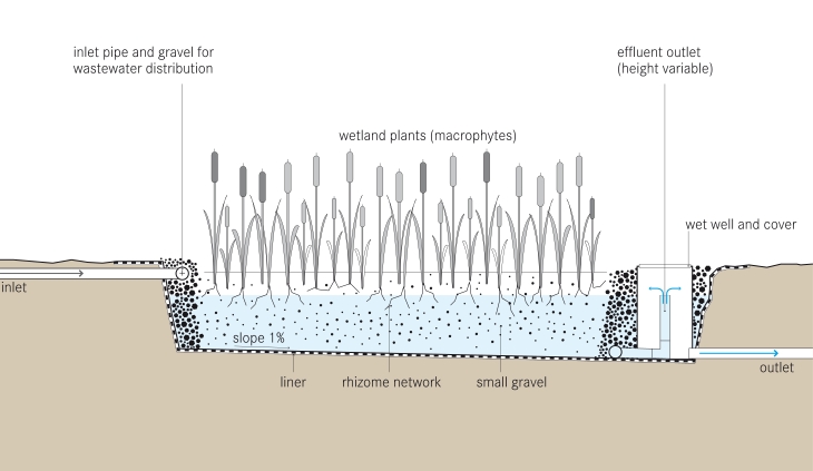
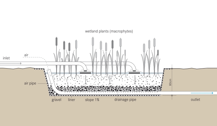
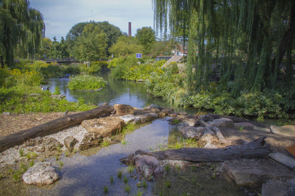
Above – A beautiful constructed wetland in action at the Lincoln Park Zoo in the USA.                             Source:http://www.acornponds.com/bog-filtration.html

What is a Constructed Wetland?

Constructed wetlands are engineered systems that use natural functions of vegetation, soil, and organisms to treat different water streams. Depending on the type of wastewater that has to be treated the system has to be adjusted accordingly which means that pre- or post-treatments might be necessary.

Constructed wetlands can be designed to emulate the features of natural wetlands, such as acting as biological-filters or removing sediments and pollutants such as heavy metals from the water. Constructed wetlands sometimes serve as a habitat for native and migratory wildlife, although that is usually not their main purpose.

There are three main types of Constructed Wetland:

  • Subsurface flow constructed wetland – this wetland can be either with vertical flow (the effluent moves vertically, from the planted layer down through the substrate and out) or with horizontal flow (the effluent moves horizontally, parallel to the surface)
  • Surface flow constructed wetland
  • Floating treatment wetland


Cost of Constructed Wetlands

Constructed wetlands are self-sustaining, and thus their lifetime costs are significantly lower than those of conventional treatment systems. Often their capital costs are also lower compared to conventional treatment systems. They do take up significant space, and are therefore not preferred where real estate costs are high. Overall, constructed wetlands are generally significantly cheaper than conventional treatment systems.

How do they Work?

A constructed wetland is an engineered sequence of water bodies designed to filter and treat waterborne pollutants found in sewage, industrial effluent or storm water runoff. Constructed wetlands are used for wastewater treatment or for greywater treatment, and can be incorporated into an ecological sanitation approach. They can be used after a septic tank for primary treatment, in order to separate the solids from the liquid effluent. Some CW designs however do not use upfront primary treatment.

Vegetation in a wetland provides a substrate (roots, stems, and leaves) upon which microorganisms can grow as they break down organic materials. This community of microorganisms is known as the periphyton. The periphyton and natural chemical processes are responsible for approximately 90 percent of pollutant removal and waste breakdown. The plants remove about seven to ten percent of pollutants, and act as a carbon source for the microbes when they decay. Different species of aquatic plants have different rates of heavy metal uptake, a consideration for plant selection in a constructed wetland used for water treatment. Constructed wetlands are of two basic types: subsurface flow and surface flow wetlands.

tilley_et_al_2014_schematic_of_the_vertical_flow_constructed_wetland

Above is an example Horizontal Subsurface Flow Constructed Wetland. Source: https://en.wikipedia.org/wiki/File:Tilley_et_al_2014_Schematic_of_the_Horizontal_Subsurface_Flow_Constructed_Wetland.jpg

tilley_et_al_2014_schematic_of_the_vertical_flow_constructed_wetland-1

Above is an example of a Verticale Subsurface Flow Constructed Wetland. Source: https://en.wikipedia.org/wiki/Constructed_wetland#/media/File:Tilley_et_al_2014_Schematic_of_the_Vertical_Flow_Constructed_Wetland.jpg

How well does this connect to this weeks reading?

The concept of Constructed Wetlands connects very well to our reading. The following are some key connections:

  • An excellent use of innovative technologies.
  • Provides a long term water management plan.
  • Address both wastewater and stormwater concerns.
  • A great example of the ecosystem approach – not only are constructed wetlands providing an ecosystem service to the human population (waste control), but they also create additional oxygen producing plants and provide a habitat for local birds and wildlife.

References:

Canada Mortgage and Hoursing Corporation – “Constructed Wetlands”                                           https://www.cmhc-schl.gc.ca/en/inpr/su/waho/waho_008.cfm

USA Environmental Protection Agency – “Constructed Wetlands”                                                     https://www.epa.gov/wetlands/constructed-wetland

Water Canada – “Constructed Wetlands: How Cold Can You Go?”                                                     http://watercanada.net/2009/constructed-wetlands/

School of Environment Sciences, University of Guelph – “Constructed Wetlands” http://www.ces.uoguelph.ca/water/NCR/ConstructedWetlands.pdf

IDP: The Integrated Design Process

The IDP was first used in the early 1990s, by Canada’s C-2000 program (program supporting advanced, energy-efficient commercial building design) and IDEAS Challenge competition (multi-unit residential buildings challenge) to describe a more holistic approach to building design. In profesional practice, IDP has a significant impact on the makeup and role-playing of the initial design team. The client takes a more active role than usual, the architect becomes a team leader rather than the sole form-giver, and the structural, mechanical and electrical engineers take on active roles at early design stages. The team includes an energy specialist (simulator) and possibly a bio-climatic engineer. Depending on the nature of the project, a series of additional consultants may also join the project team from the outset.

Some of the key advantages of the IDP are cited below:

  • Goal-driven with the primary goal being sustainability, but with explicit subsidiary goals, objectives and targets set as a means to get there.
  • Facilitated by someone whose primary role is not to produce the building design or parts of it, but to be accountable for the process of design.
  • Structured to deal with issues and decisions in the right order, to avoid locking in bad performance by making non-reversible decisions with incomplete input or information.
  • Clear decision-making for a clearly understood methodology for making decisions and resolving critical conflicts.
  • Inclusive—everyone, from the owner to the operator, has something critical to contribute to the design and everyone must be heard.
  • Collaborative so that the architect is not simply the form-giver, but more the leader of a broader team collaboration with additional active roles earlier in the process.
  • Holistic or systemic thinking with the intent of producing something where the whole is greater than the sum of the parts, and which may even be more economic.
  • Whole-building budget setting—allows financial trade-offs, so money is spent where it is most beneficial when a holistic solution is found.

Below is a graphic representation of the IDP Process:

2016-10-17

References:

http://www.nrcan.gc.ca/energy/efficiency/buildings/eenb/integrated-design-process/4047

http://iisbe.org/down/gbc2005/Other_presentations/IDP_overview.pdf

http://www.infrastructure.alberta.ca/content/doctype486/production/leed_pd_appendix_7a.pdf

MEASURES OF SUSTAINIBILITY APPLIED TO THE CIRS BUILDING AT UBC

MEASURE 1: Design & Innovation

CIRS is aimed at being a regenerative building whose existence will improve the quality of the environment. This building contributes to reducing the energy use and carbon emissions. The building sequesters more carbon than the construction and decommissioning of the building will produce overtime.

MEASURE 2: Regional/ Community Design

Roof of the building is designed to be a self sustaining ecosystem where the vegetation includes indigenous plants for local birds and insects.

MEASURE 3: Land use and site ecology

The area of land that CIRS is built on improves the quality of the surrounding environment. It cleans the water it receives, captures heat that would otherwise be emitted to the environment and harbours vegetation that enriches the surrounding ecosystem.

MEASURE 4: Bio-climatic Design

Much of the heating in CIRS comes from the ground and from the heat exhausts from the building next door. Significant amount of the ventilation is from wind and a large part of the electricity is from the sun. This is really a building that survives within the natural flows of the environment.

MEASURE 5: Light and Air

Building is oriented to make optimal use of the daylight received by the site. The higher location of the windows allows for deeper penetration of the daylight into the interior spaces of the building. Solar shades and spandrel panels help control the glare and heat gain from the sun.

MEASURE 6: Water Cycle

All the water used in the building comes from the rain and the water leaving the building is of a better quality than the rain that is received on the roof. CIRS cleans the quality of the water and achieves a net positive in terms of water quality.

MEASURE 7: Energy flows and future energy

Uses geo exchange and solar energy. Uses waste heat from the Earth and Ocean Sciences building next door and captures the energy that would other wise be emitted to the environment.

MEASURE 8: Materials and construction

Wood used for the main structure of the building sequesters 600 tonnes of carbon. This is more carbon than the emissions from all the other construction materials, construction processes and decommissioning and the end of the lifetime of the building.

MEASURE 9: Long life, loose fit

CIRS is designed with ecological, social and economic rationale. Not only does it aim to improve the quality of the environment overtime it also aims to improve the health of its occupant. Flexibility, modularity, adaptability and expandability principles were included in the design of CIRS to ensure that it can adapt to new uses and respond to future space configuration requirements without the need of expensive and wasteful renovations.

MEASURE 10: Collective wisdom and feedback loops

In many ways CIRS is a research project that is intended to identify which processes and techniques work well and which ones have more scope for improvement. Research and observations of the way the building functions and interacts with the environment are ongoing and this knowledge will be used to improve sustainable designs of buildings in the future.

Spam prevention powered by Akismet