This was the most troublesome part of our analysis. Setting up a Network Analysis is very particular, and the user has to be able to correctly input their own parameters. Here is a step-by-step guide to setting up a shortest path network analysis along a given road network.
- Create new feature dataset
- Open ArcCatalog and navigate to your gdb
- Right-click on the gdb, hover the mouse over ‘new’ and select ‘feature dataset’
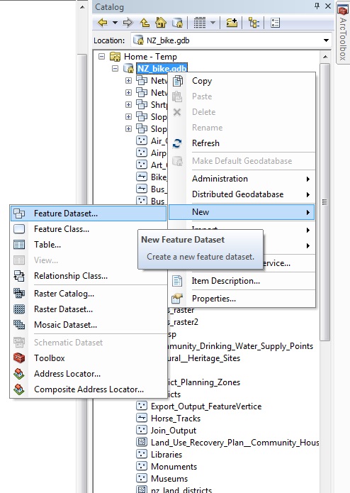
- Give it a relevant name
- Assign it the same geographic projection as the rest of your data
- Click ‘next’ twice, then ‘finish’ (nothing needs to be changed for vertical projection or XY tolerance)
- Import relevant files
- Right-click on the new dataset
- Hover over ‘import’ and select ‘feature class (single)’
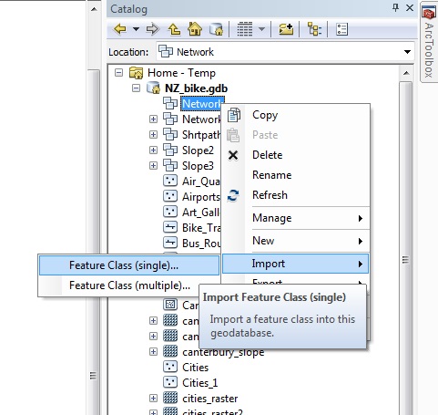
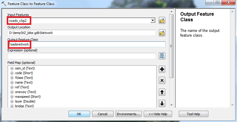
- Select the relevant road feature and give it a new name
- Create Network Dataset – most important part
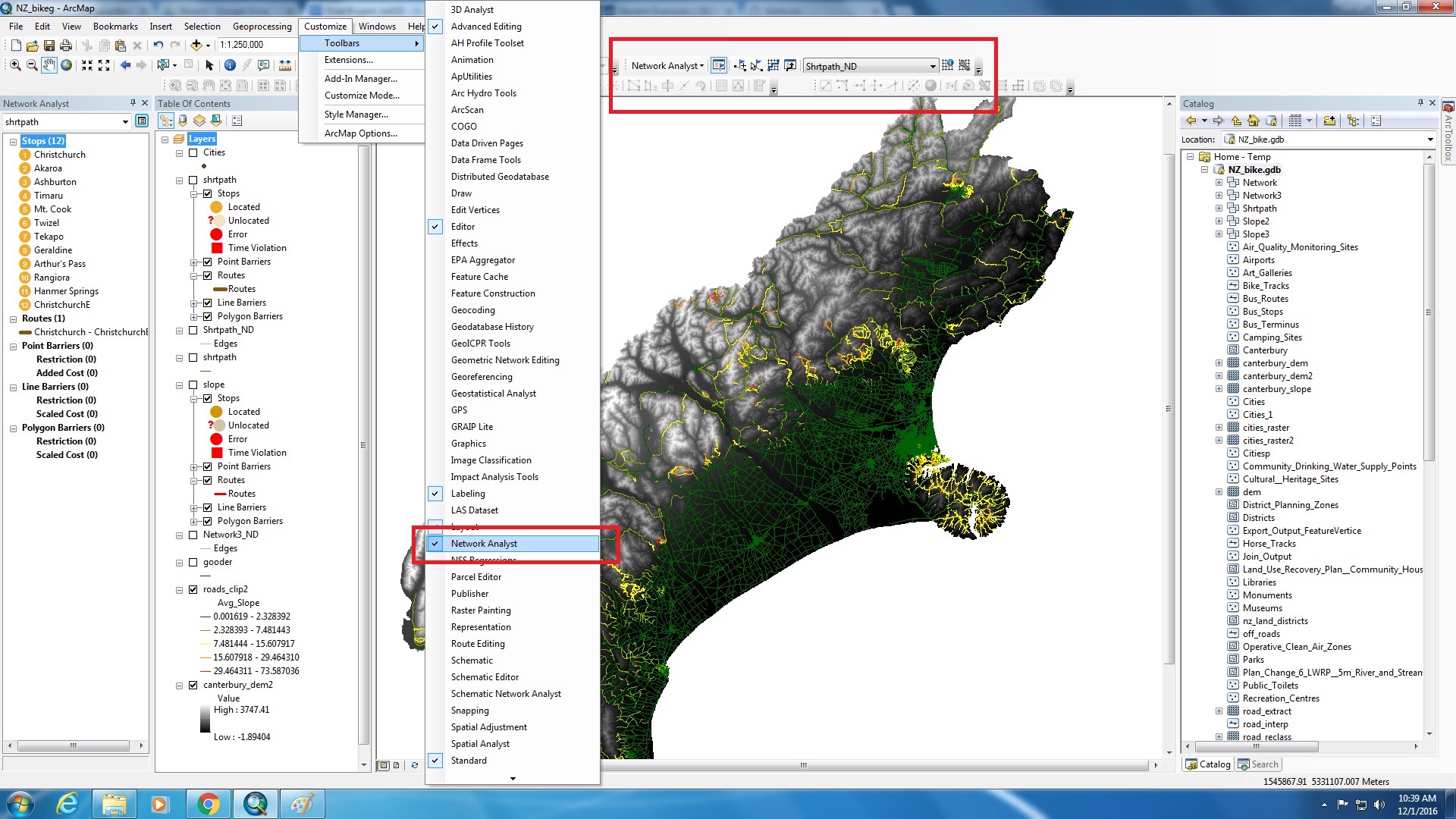
- Ensure Network Analysis toolbar is checked under ‘Customize’ -> ‘toolbars’. Click on it if it is not
- Make sure the toolbar is visible and drag it into the top margin
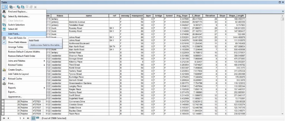
- The road length data is most likely currently stored as ‘Double’. To be able to use it in a Network Analysis, it needs to be in ‘Integer’ format. So, we need to convert it. Open the attribute table of the roads file you imported into the feature dataset
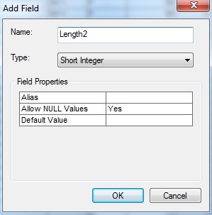
- Click on ‘Table Options’ and select ‘Add Field’ and rename it something appropriate (we used Length2), ensuring that the field type is ‘Short Integer’.
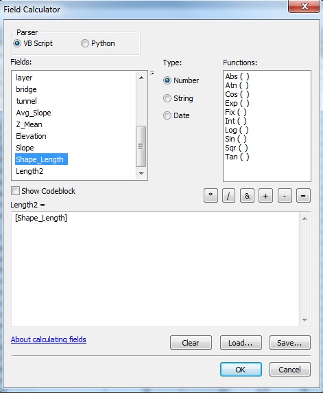
- Right click on the top of the new field and select ‘Field Calculator’.
- In the window that pops up, select the shape length file and click ‘Ok’. This populates the new integer length field, and will be relevant later.
- Right-click on the feature dataset, hover over ‘new’ and select ‘Network Dataset’
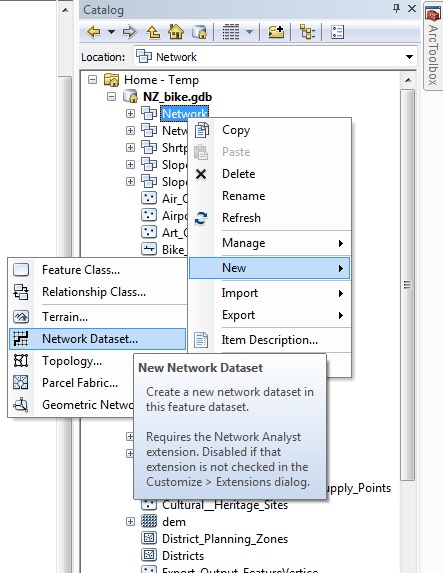
- Rename the dataset something appropriate then click ‘next’
- Ensure your imported road is checked then click ‘next’
- Select ‘yes’ to model turns and click ‘next’
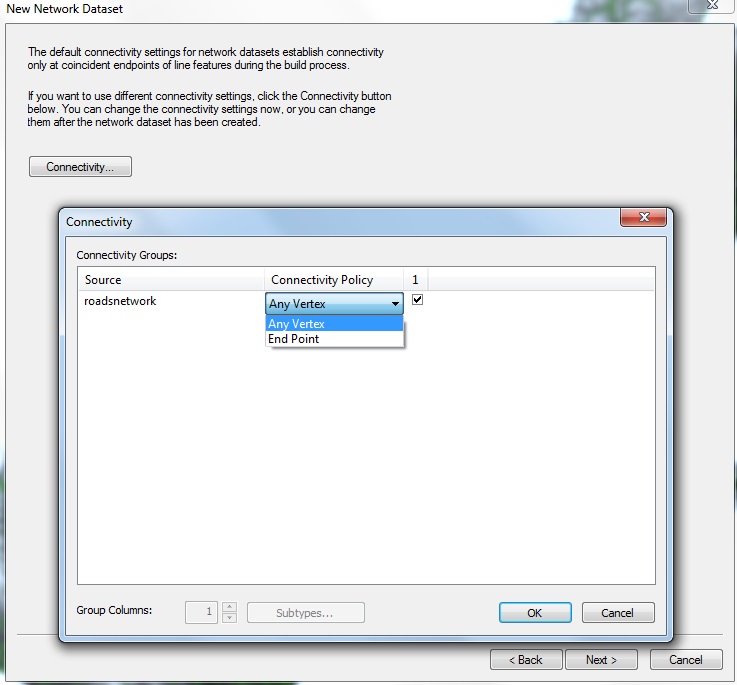
- Click the box that says ‘connectivity’ and change ‘end point’ to ‘any vertex’. This changes where vertexes and junctions are located. Click ‘Next’.
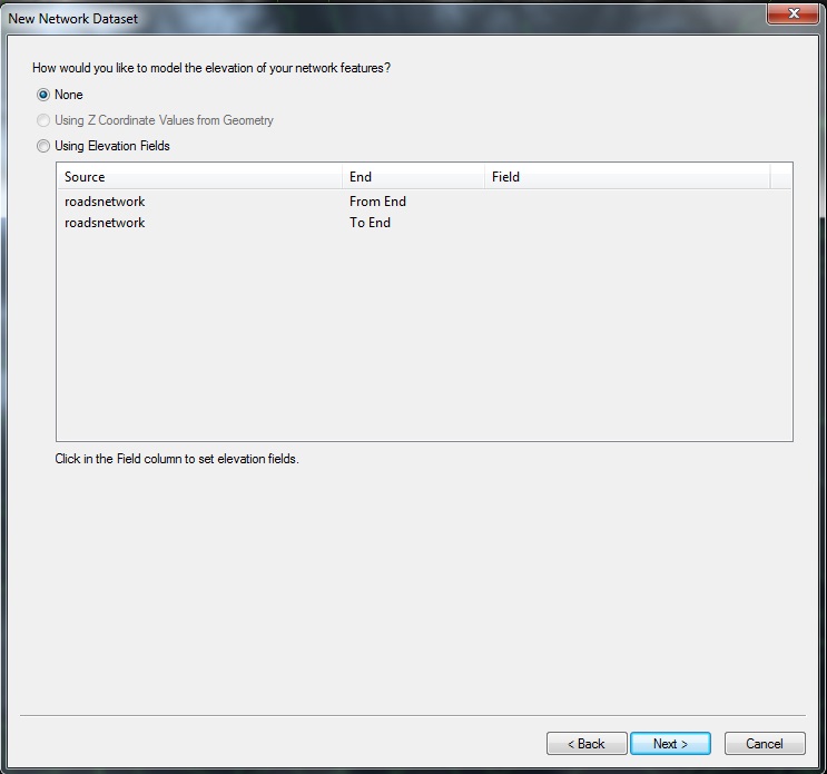
- For an unknown reason, Network Analyst is not able to model the route if using an elevation from a field in the attribute table, so, for simplicity, click ‘None’.
- This next step is where things can get tricky. What you now need to do is specify the rules or parameters that govern the analysis. You should arrive at a screen that looks like this.
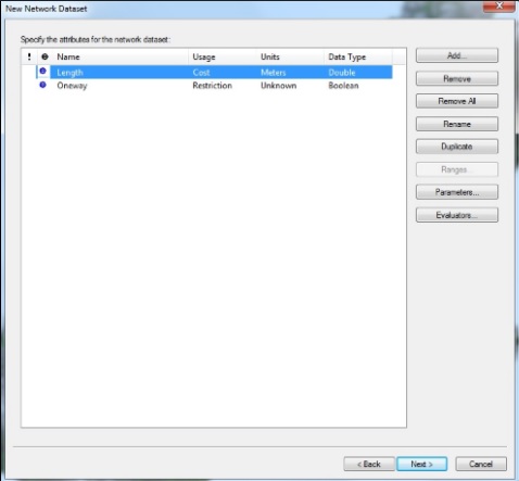
- For our analysis, because we were considering a cyclist route, we immediately removed the ‘oneway’ rule, because that did not apply to us. If you are setting up a network for a vehicle that needs to obey one way traffic laws, do not delete this field.
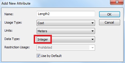
- We want to consider ‘shortest path’, so click on ‘Add…’. Under Name, type in the name of the length integer field that you created in the attribute table earlier. The Usage Type should remain ‘Cost’, as we want the cost to increase the further the route has to travel. Select appropriate distance units, change data type to ‘Integer’, check ‘Use by Default’, and click ‘Ok’.
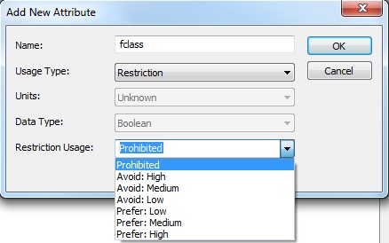
- At this point, if you have restrictions (ie, cannot go on a particular street type), you can add restriction rules. Click ‘Add…’. Under Name, type in the name of the field that relates to the restriction (in this example of not being able to go on a particular street type, our attribute table stored road type in a field called fclass). Select ‘Restriction’ as usage type, and choose the type of restriction usage; whether you want to altogether avoid the given feature (prohibited) or simply avoid it.
- Once you have added all your rules (for the simplest shortest path case, all you need is a cost rule for adding length), click ‘Next’.
- Under ‘Travel Mode’, input your mode of travel, select your method of travel (under ‘Type’), choose the impedance attribute; for this example it is the length of the roads. If you have a rule in units of time, you can input a time attribute and it will calculate travel time as well as shortest distance. The right hand side tab allows you to select any restrictions you have input, and apply them to the given network dataset. Once you have applied all your parameters, click ‘Next’.

- Choose ‘yes’ to driving directions and click ‘Next’. Do not select ‘Build Service Area Annex’.
- Click ‘Next’ one more time, then ‘Finish’.
- A pop up window will appear asking if you want to build the dataset now, select ‘Yes’.
- Congratulations! You have built a Network Dataset. Now, to build the route.
- Ensure Network Analysis toolbar is checked under ‘Customize’ -> ‘toolbars’. Click on it if it is not
4) Create a new route
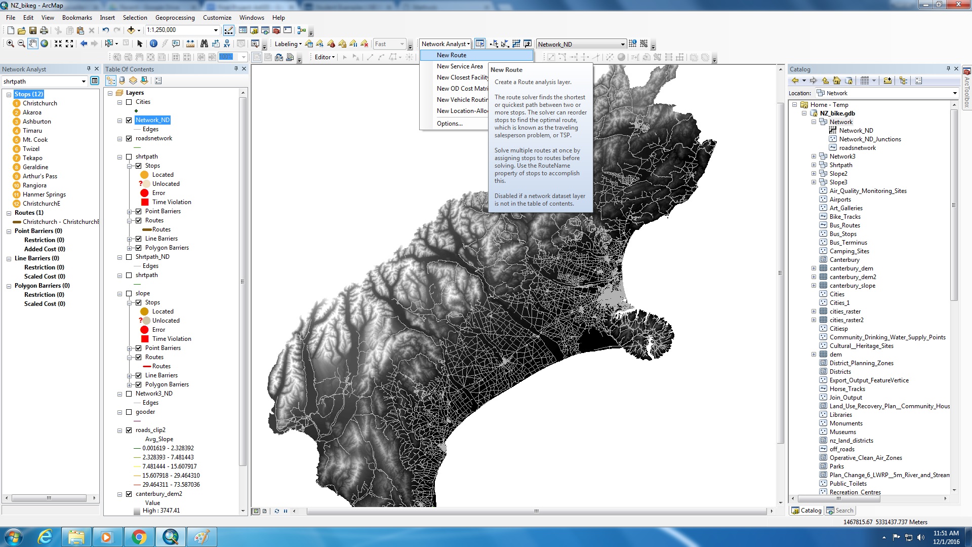
- On the top margin, where the ‘Network Analyst’ toolbar is located, click on the dropdown menu and select ‘New Route’.
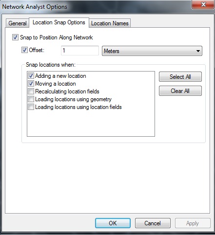
- Also under the ‘Network Analyst’ dropdown menu, select ‘Options’, navigate to the ‘Location Snap Options’ tab and select ‘Snap to Position along Network’. This ensures that you won’t have unlocated stops.
- Now you can add your stops to the map. Click on Create Network Location Tool (next to the dropdown menu) to input route stops.

- Click on the locations that you desire.

- Once you have input all your stops, click on ‘route properties’, on the ‘Network Analyst’ sidebar
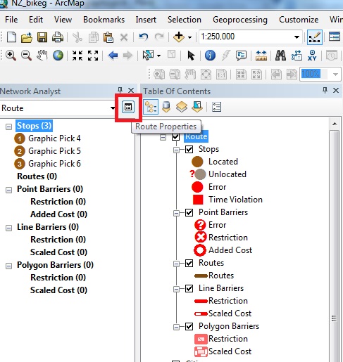
- Navigate to the ‘Analysis Settings’ tab and ensure that the impedance and restrictions parameters are accurate. Select ‘Reorder stops to Find Optimal Route’, and select ‘Preserve First’ and ‘Preserve Last’ if desired. If all information is correct, click ‘Ok’.

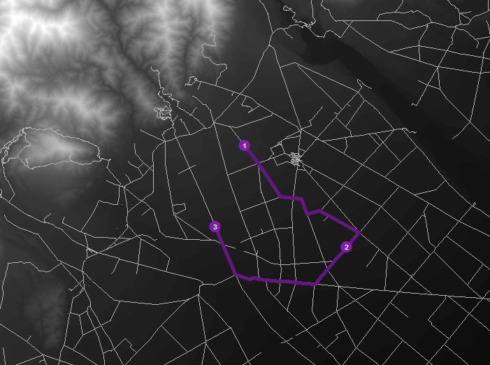
- You are now ready to solve the route. On the Network Analyst toolbar at the top of ArcMap, select ‘Solve’.
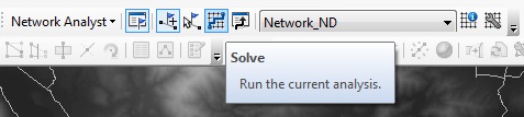
- You now have a completed route, with stops reordered if necessary. Well done.