Here is all the progress posts on my modelling of toothless. I’ve never used UBC blog’s before and sadly could not figure it out…
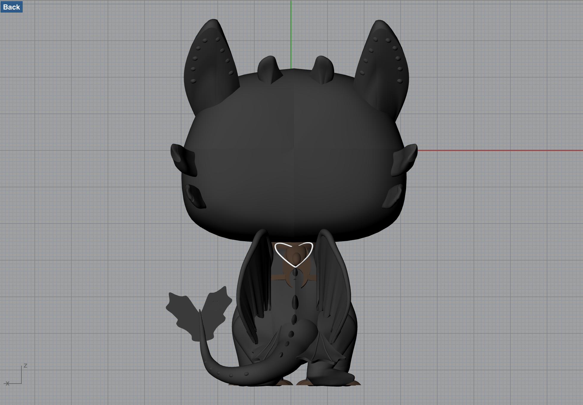
– Brooke
Here is all the progress posts on my modelling of toothless. I’ve never used UBC blog’s before and sadly could not figure it out…
– Brooke
After a failed attempt with the first Hulk I made, Keara and I decided to team up to remake our models. We ended up remaking the whole model in rhino and I’m very happy with it! It was super helpful to be able to split up the pieces and tackle each one individually. We could then learn from each other and we were able to help each other problem solve when we ran into issues. We completed the model on Friday and then we joined the pieces on Saturday. The joining process surprisingly went smooth. The most difficult part to join was the shorts of the Hulk, but after remaking the bottom of the shorts it came together. It was now time to print!
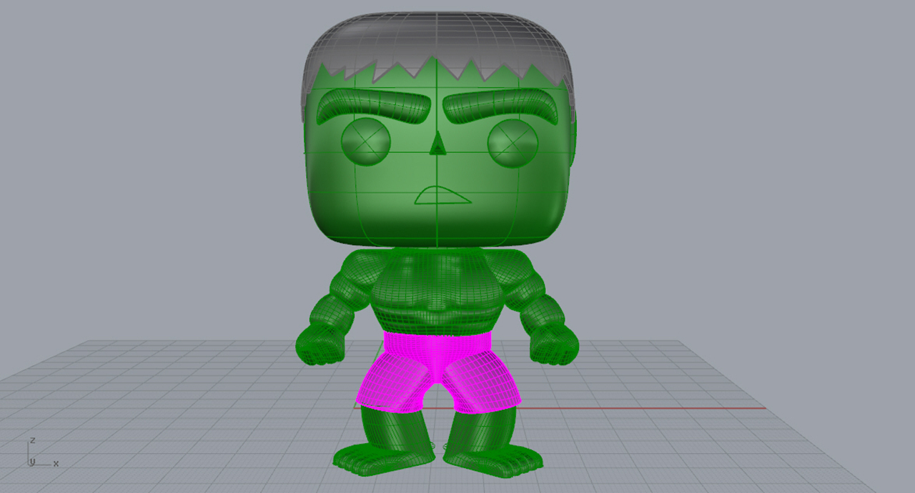
He’s watertight!
Ready to print
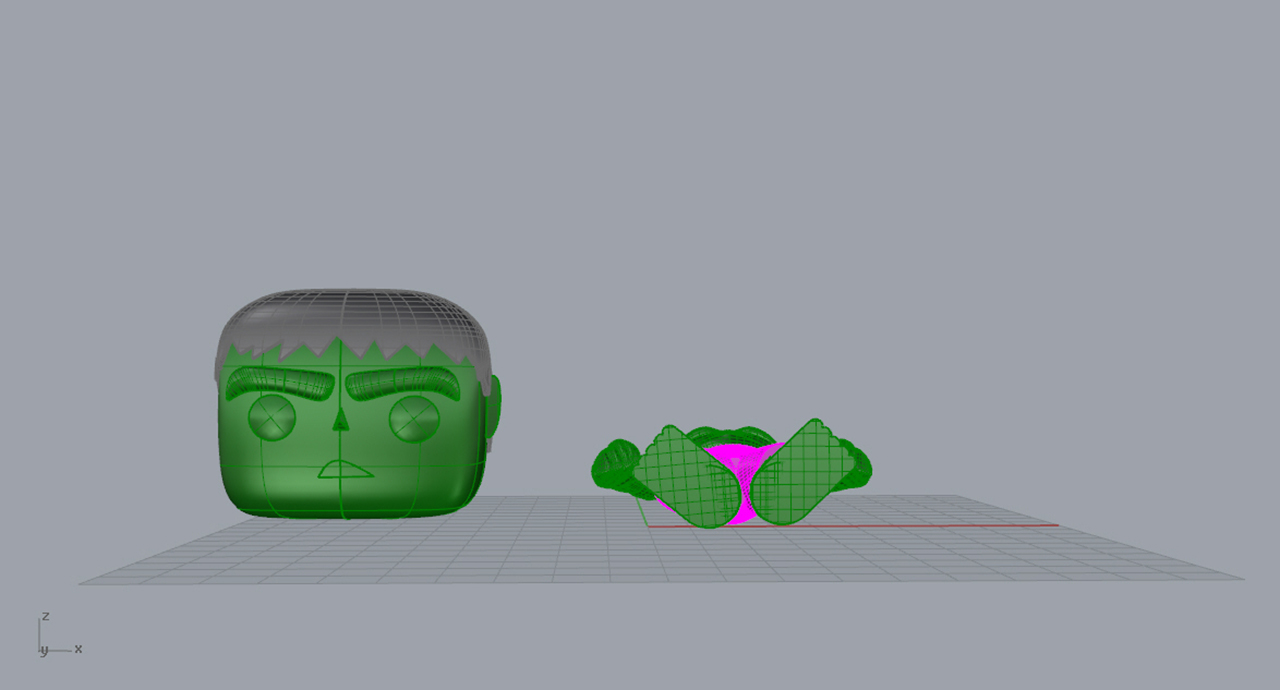
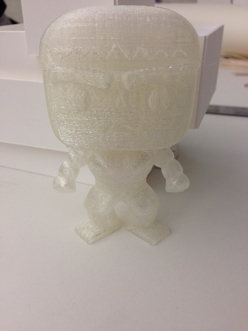
We went to Lassere to print and for the most part it went well. We first tried printing both Hulks together, however we realized as soon as it started that we would not get good results because the glue was cooling too much by the time it got to each piece. We decided to print each head and body individually, which ended up working much better. We set the body up to print horizontally with the front facing up. This created a much smoother front, as no support material covered it. However, the back did lose some detail because of the support material that was built under it. The head printed well with very little imperfections. Overall, I’m happy with the final product.
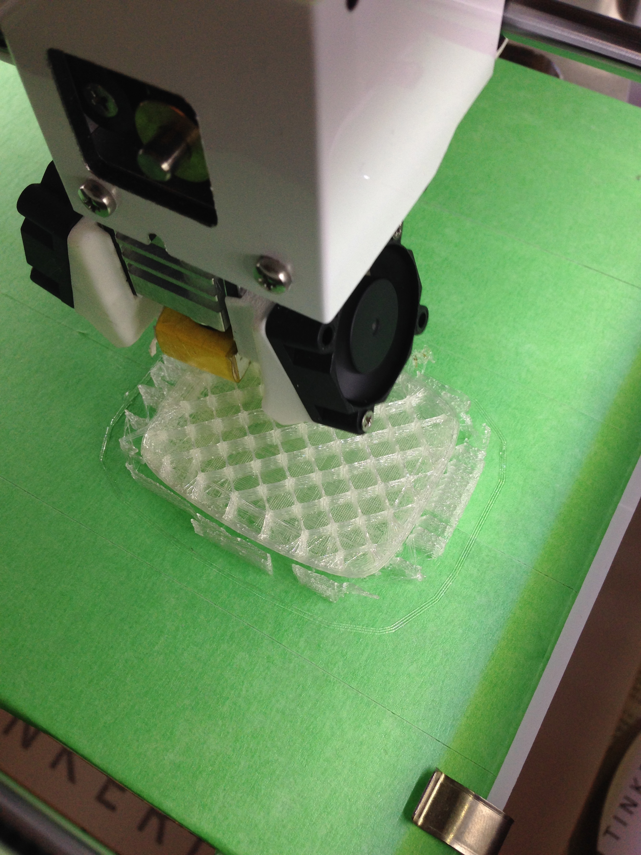 Printing the head
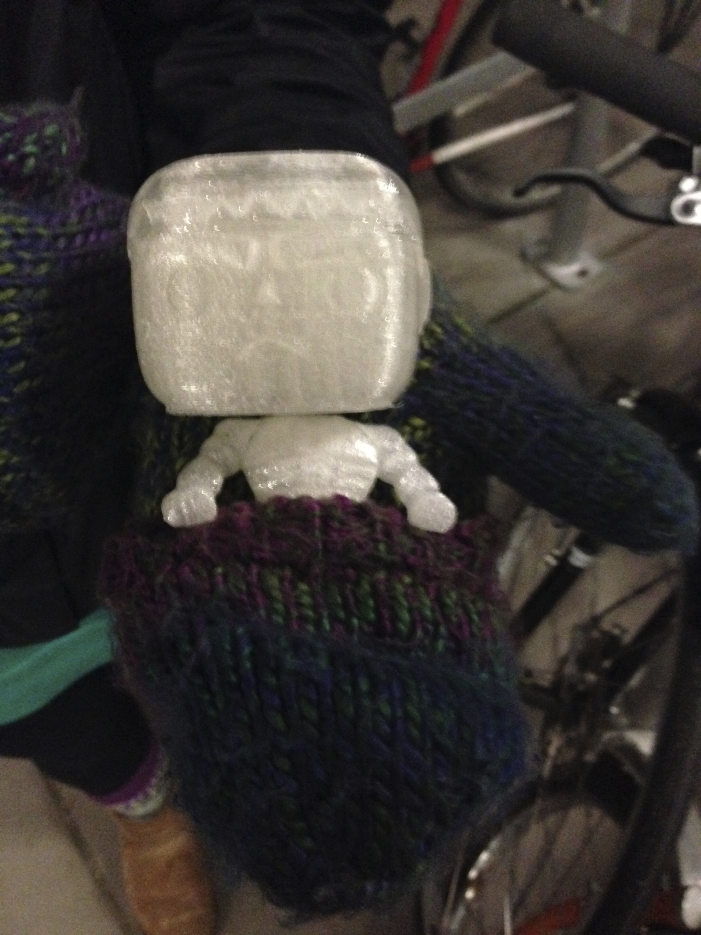
 Abs of steal
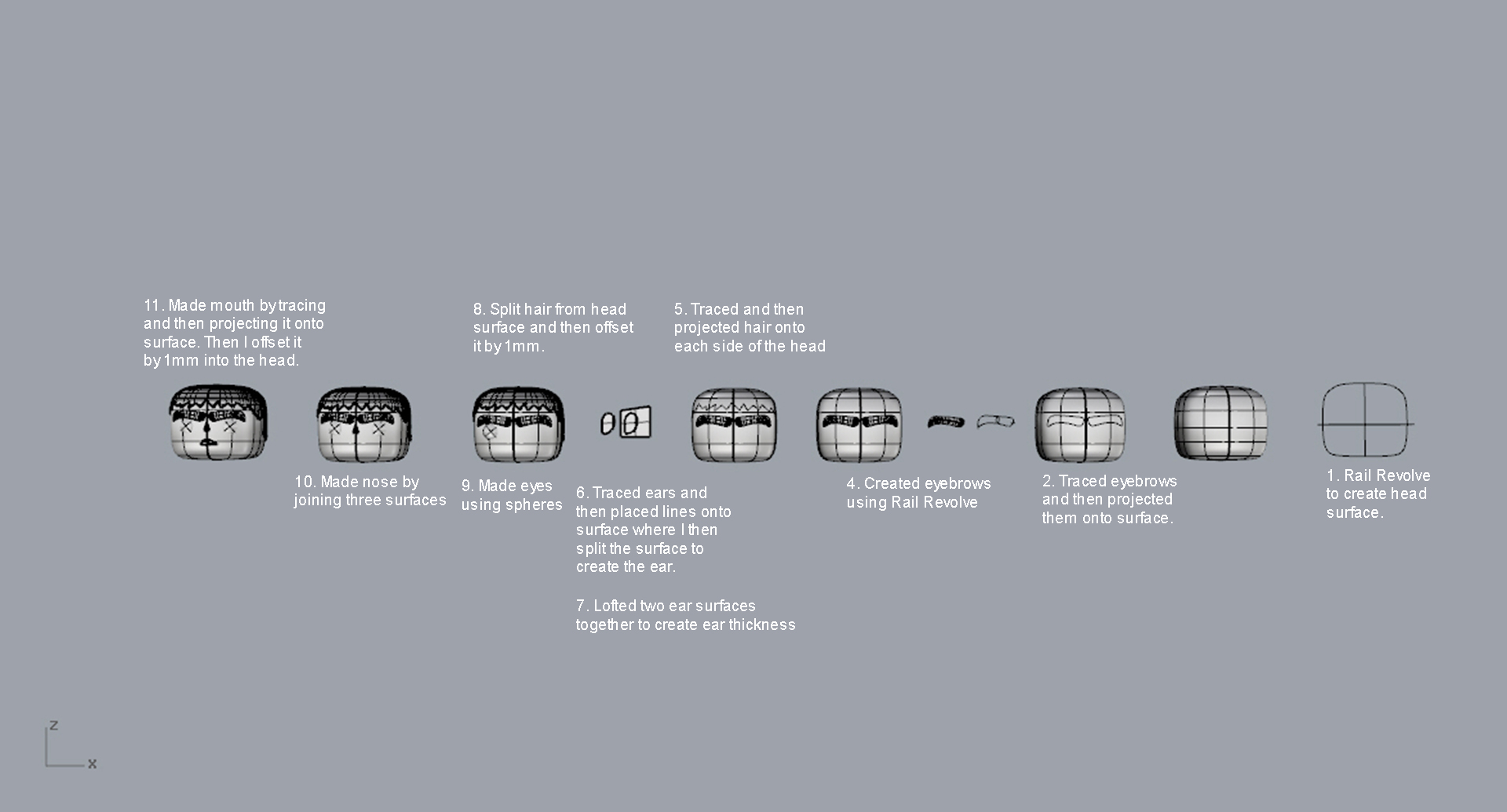
The first head I tried to make was way more complicated than it had to be and it did not work out (I made it using a bunch of different lines and then lofting them together). The solution was using three simple lines and then the “rail revolve” command.
Once I made the head I could then add the hair, eyebrows, ears, eye, nose, and mouth. Check out the image I attached to see the whole process!
So I’m pretty proud of Mr. Hulk’s eyebrows. I spent many hours trying to figure these brows out and I finally go it! For the first attempt, I traced the eyebrows and then I created a bunch of curved lines that ran perpendicular to the outline of the brow. I lofted these together and it worked, but it didn’t have the fluidity I wanted, it once again looked choppy. I then spent some time playing with the “rail revolve” tool. I didn’t think it would work, but by manipulating the traced brow in a certain way it eventually did!
The process:In order to get the curve in the eyebrow that our hulk model has, I projected the traced brow line onto the head. Then I created a circle in the middle of the brow (I had to make sure it was intersecting the lines on each side) and split the brow in half. I needed to have the circle in order to use the “rail revolve” tool. Once I split it in half, I then split it into quarters by drawing a line through two points on the brow. Now I had two open lines that were running from the circle on each side, which meant I could now use the rail revolve tool. It worked perfectly! I then joined the surface together and I had a perfectly smooth eyebrow. The best part is that when I actually figured out how to do it, it only took a minute to do.
Eyebrow making process
It was finally time to print the figure on our brand new Tinkerine 3-D printers. Unfortunately, I am not thrilled with the results. The clear material feels cheap, and the support material left rough edges that cannot be removed without damaging the figure. I plan to print again using the powder printer, and hope to get better results.
One thing that I will do differently is orient the glasses so that the front of the frames are face down on the ground plane. This should minimize the amount of support material that they need. As you can see, the way that I oriented them in my first attempt resulted in them being completely encased in support material.
Once I had all of the individual parts of my figure made, it was time to put them together. The commands I used the most for this were join, boolean and blend surface. Below, you can see one of the ‘locks’ of hair being blended to the rest of the hair. I first had to split a hole into the main hair by drawing a curve, projecting it onto the hair and using the split command.
Another command that came in useful for the final joining was match surface. I only modeled half of most of my figure, and when it came time to mirror and join the two halves of the torso and head, there was a visible seam running down the middle. Matchsrf made short work of smoothing out the seam. The two halves were then joined.
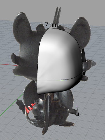
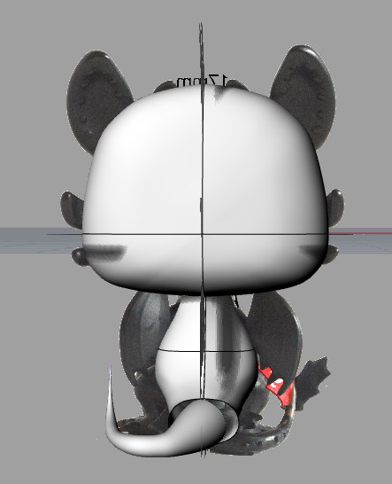
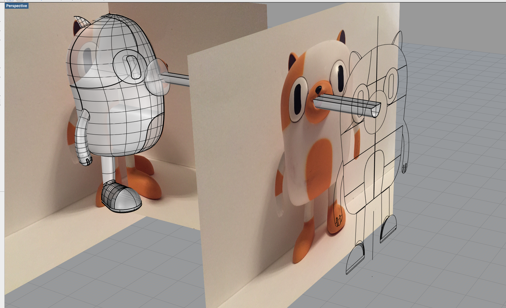
I started modelling by creating the head. To do this, I traced a photo of the model along the axis cutting directly through the face on the model (The front, horizontal line seen in below photo) on the right half of the model. I then traced the vertical axis so that it was cut in half by the horizontal axis. I traced one more line following the right side of the head, along the ears, down the side and to the bottom. I then used Network Surface and mirrored the object to create a whole head.
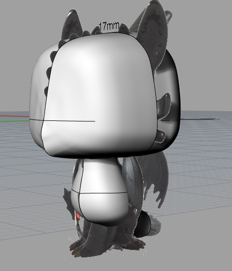
I created the body next. First I traced along the same vertical axis that divides the head along the ridge of spikes. I traced from the top left corner to the bottom right corner, and then the other side to create 2 rails. I then drew the shape of the body in 3 lines to create the curves of the right side. I then used Sweep2 to connect the 2 rails with the shape lines.
Afterwards, I created the tail by forming the shape with circles and lines and using the pipe command to connect them.
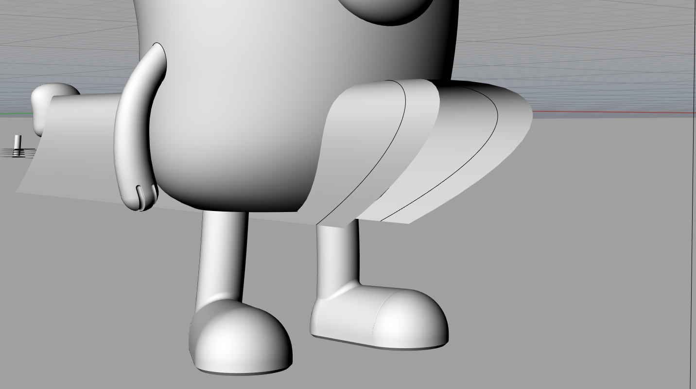
Next, I began to form the legs. I did this by creating 2 circles (one for the base of the foot and one for the shoulder joint), and then forming the exterior shape with curves and new work surfacing them. I have also started to form a foot with claws for the bottom of each leg.
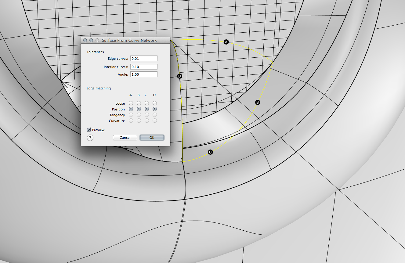
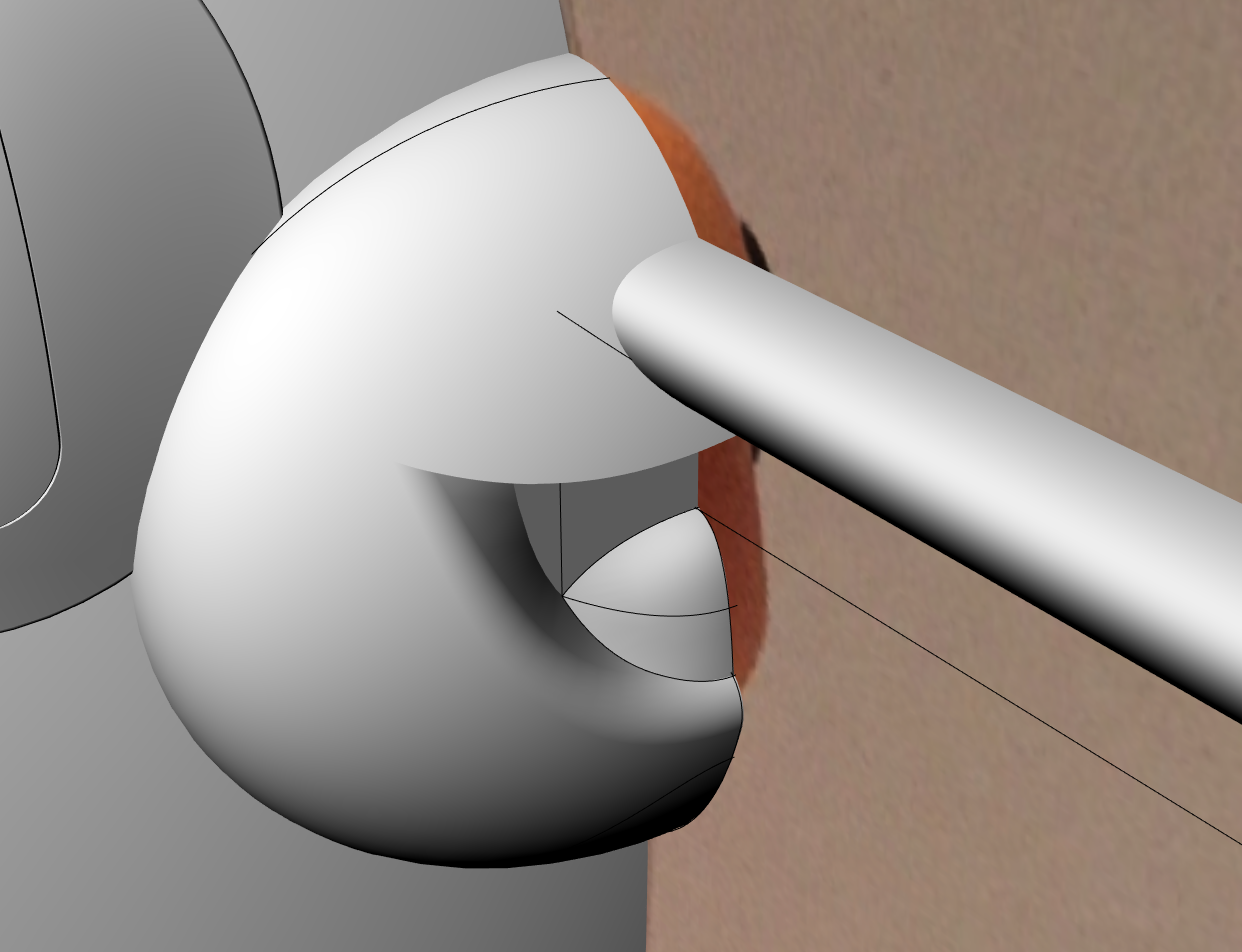
Next, I created the main ear. I did this by forming several circles in the shape of the ear and using Loft to connect them.
(Jen Bowen)
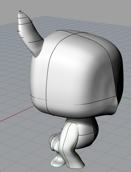
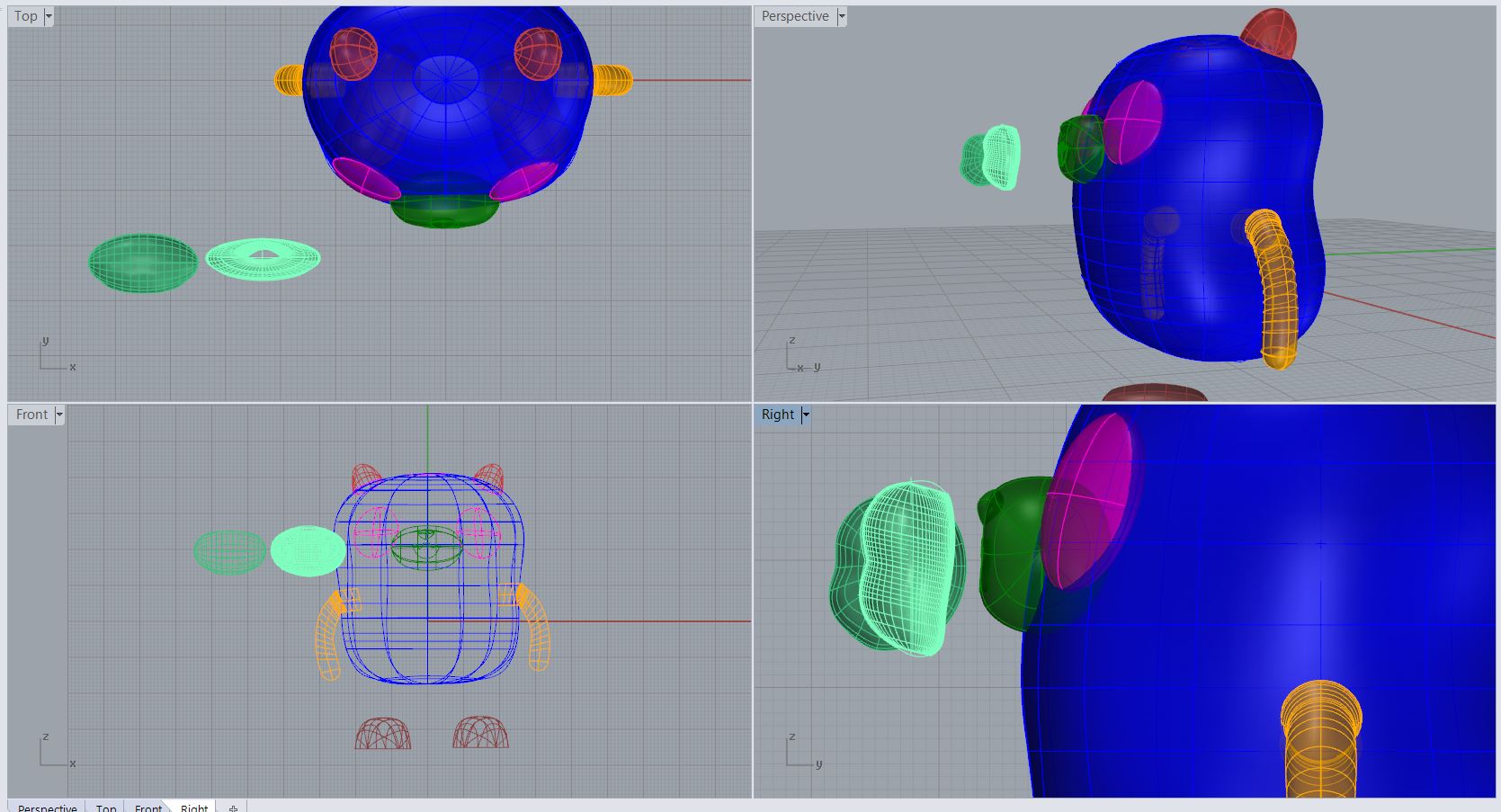
Leanne- Cake is almost done being modelled minus some work that needs to be done on details and creating closed surfaces. In our last post we were experimenting with creating the shape of the body and in this post I will show how I created the extremities and details (mostly commands such as surface network, ellipsoid by diameter, sphere by diameter, sweep2, boolean union, split, join, and by manipulating control points on objects).
Above is the nearly finished version of Cake.
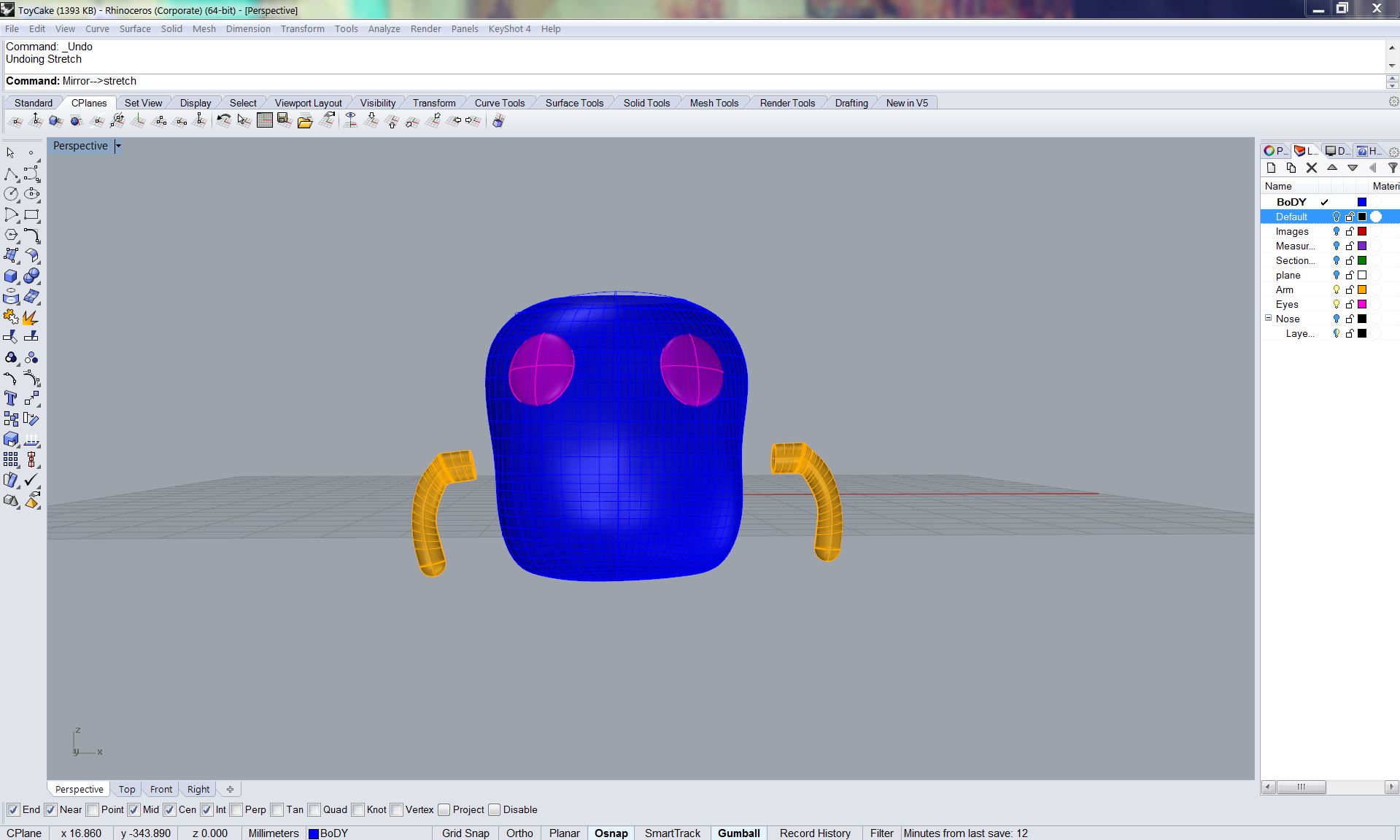
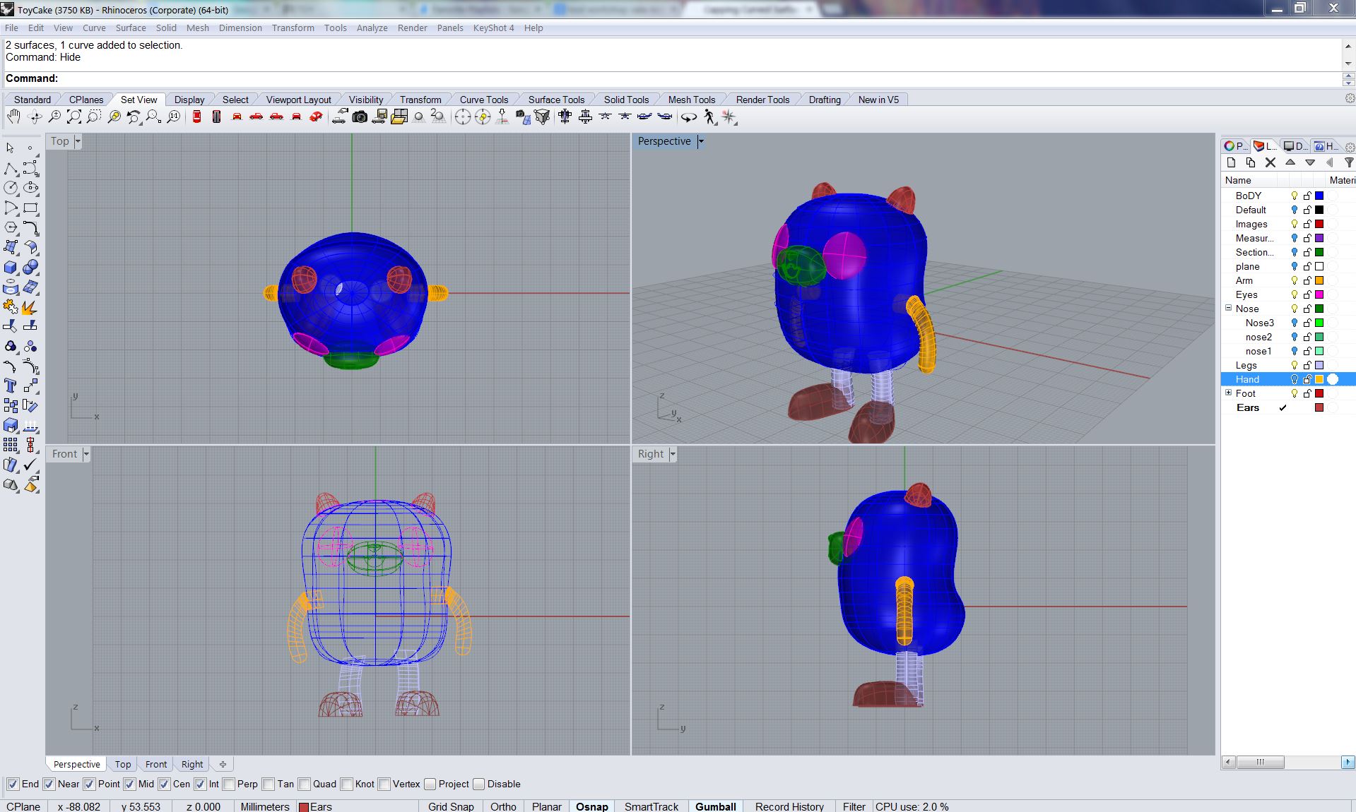
I started with the arms and eyes. The eyes were simply made with the command “elipsoid by diameter.” I took measurements directly off of the doll and made the elipsoids to this dimension. The arms were made by tracing a photo of the front view of Cake. I traced the arms and compared this with measurements directly from the model. I placed an elipse at the bottom of these two lines and did the Sweep 2 command. I then capped the holes to have closed objects.
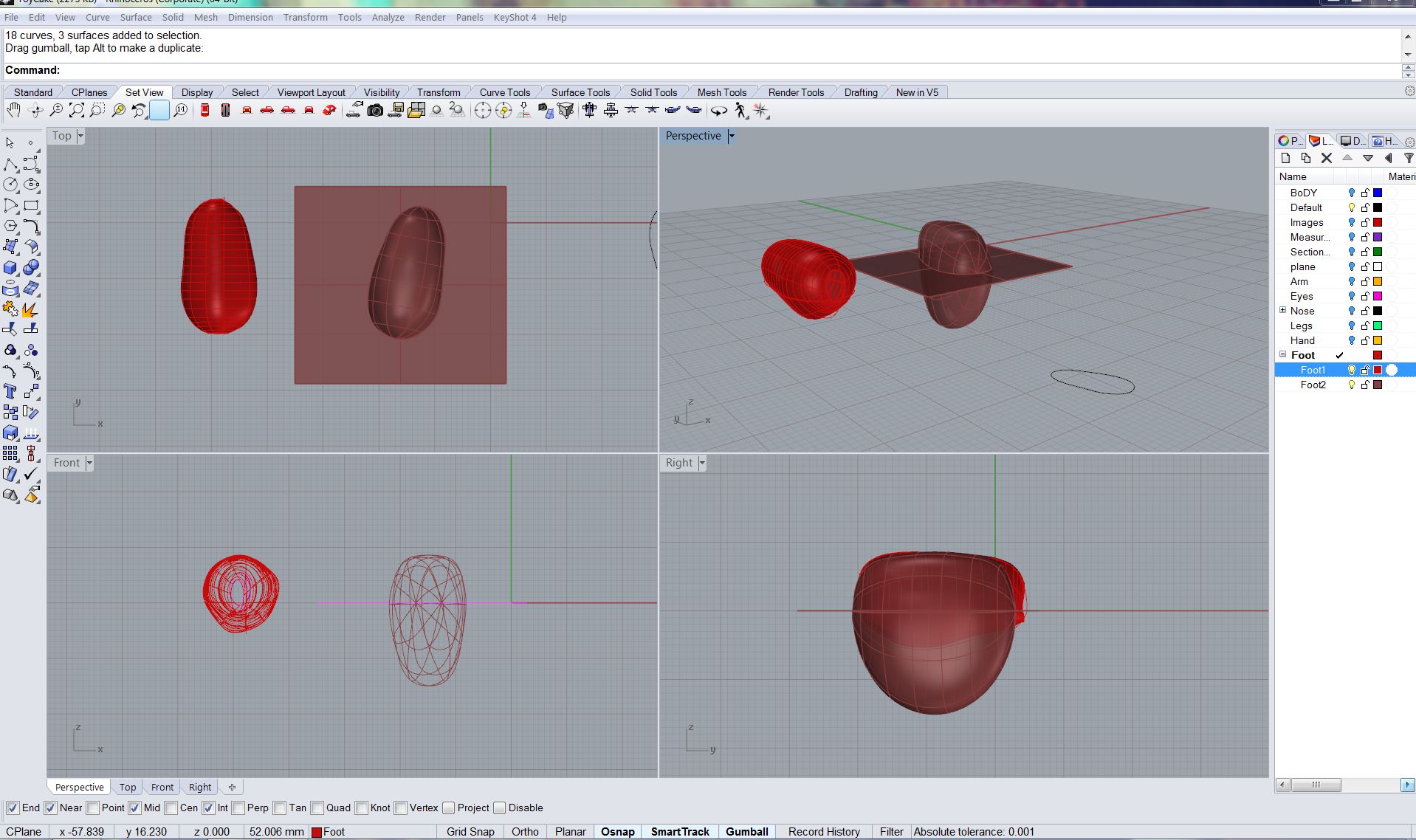
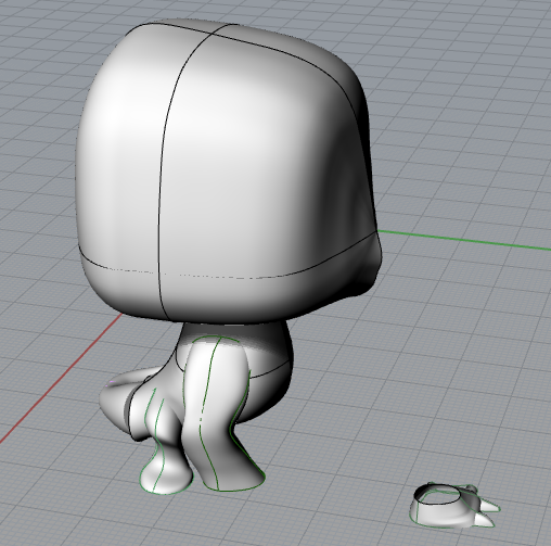
Next I attempted the feet. I struggled with this a little bit. First I attempted a method using thenetworksrfc command (the brighter red foot on the right). I traced the shape of the bottomof the shoe off of the model, then created a wire frame of the shoe based off of photos and measurements. It was really hard to accurately measure and I realized I was getting too detailed. I was getting tired and the foot came out really terribly. I decided to try a new method. This was to manipulate control points on an ellipsoid. I manipulated them to match up with the actual footprint of cake and the outcome was much better than the first. I trimmed the new shoe with a plane (as you can see in the photo) and then capped the object.
Finally I worked on the nose. It took a few tries to get it right. The first attempt was to manipulate control points on a sphere. The second was to take the profile, use photos and measurements and create a wireframe to run the networksrf command with. This did not work for me. It was too finicky and a waste of time. I ended up going back to manipulating surface points to get a desirable outcome. I did the same with the tip of the nose and have yet to figure out how to join these to objects.
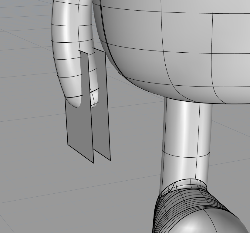
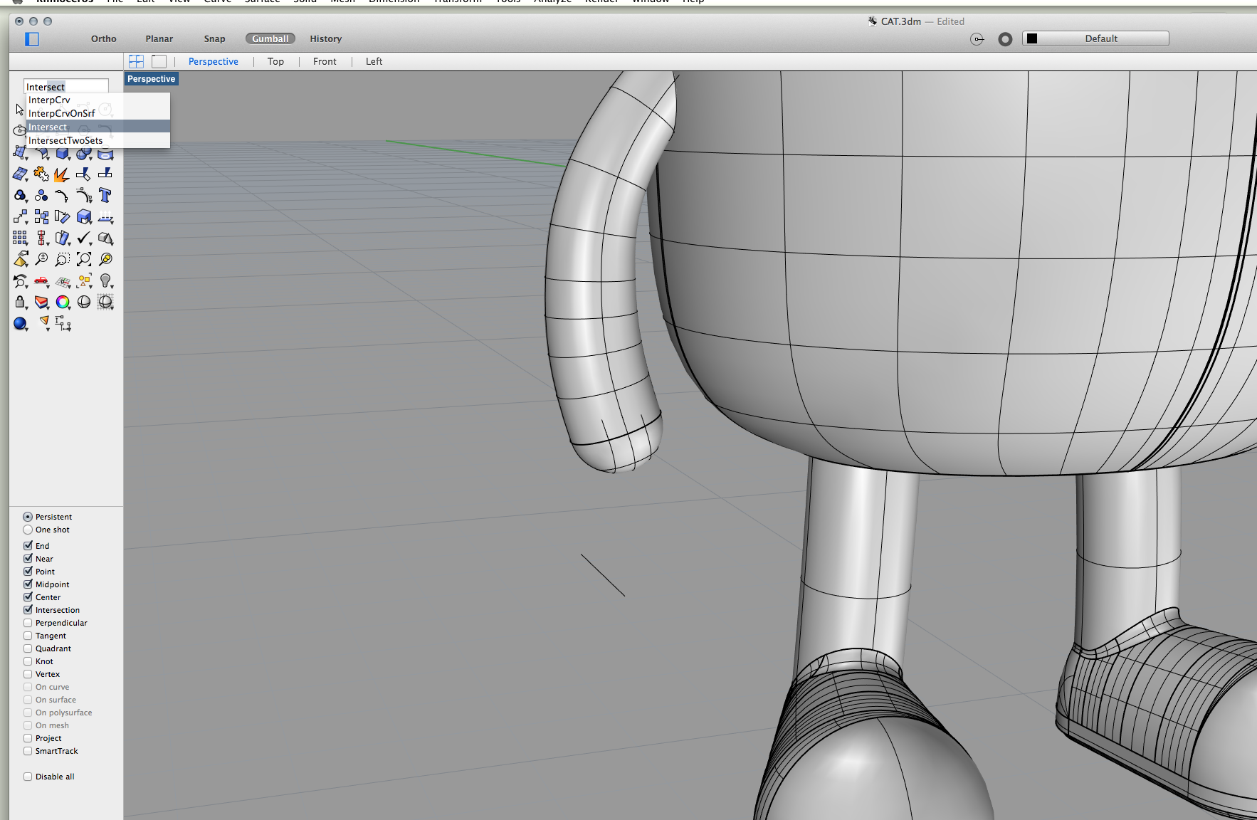
Viktoria – My approach was to combine tools like pipe, surface curve, patch, loft. I ran into issues in making the fingers – I attempted to pipe separations and then split the difference then fillet to smooth them but the effect was not entirely successful in making the hands accurate to the actual object. I also had to reconsider some approaches when I considered the rendering requires, so make separate pieces that would be the different colours of the model. To make the face I traced the eye in front view from the photo then extruded through the torso booleaning difference to create a circle that warped to the contours of the torso then making surface curves to create the shape. I had initially attempted to create the eyes using spheres but found that method inaccurate and harder to control. I will rework the facial details in my next iteration for further accuracy and fidelity. This current model is not ready for 3d printing yet as it is not water tight – there are some ‘messy’ bits on the inside that need to be cleaned up and edges that need to be closed.
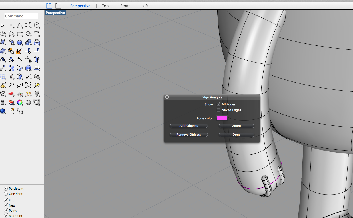
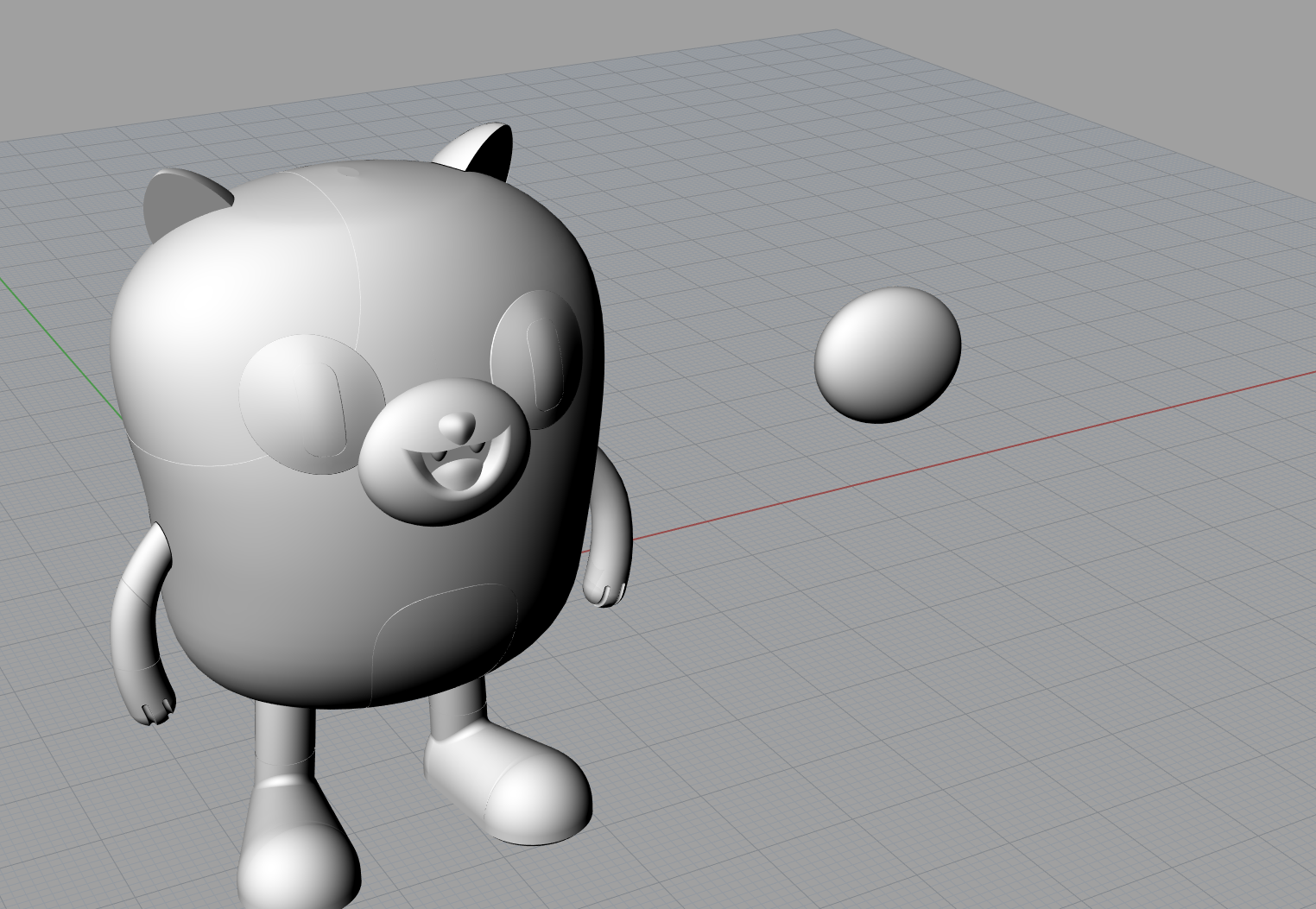
In playing around with my renderings I had a few different approaches – I used matte paint materials for one model and metal paint materials for another. The matte version (though more like the actual model) came out looking dull in the render. The shinier metal paints gave the rendered model more dimensionality and liveliness but is less true to the actual model. I also realized in rendering that I am missing an orange arm patch on one arm, and that the back of the mouth/throat needs to be separated in my Rhino model so that I can colour it separately
l


After experiencing some difficulty accurately modelling the armor components of our previous toy (Cyborg) and Daozhen and I decided to switch toys.
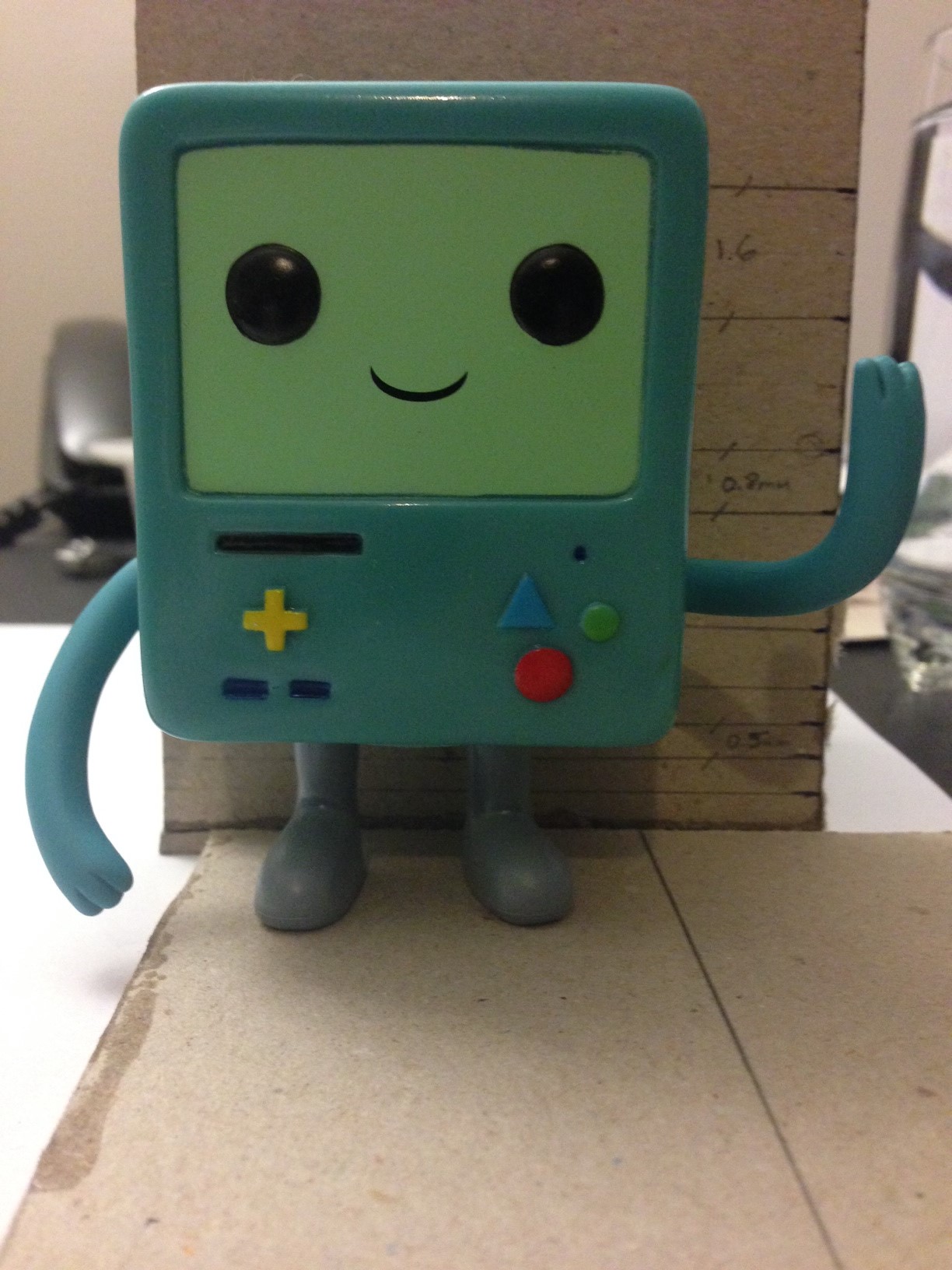
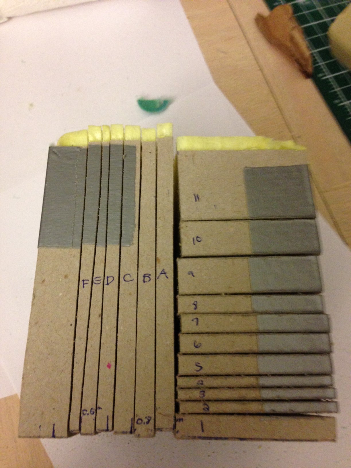
With our new toy (BMO) we repeated the same initial steps we had taken previously – gluing it within a box container, filling it with foam and cutting it using a bandsaw. That said, we were more cautious this time around in deciding where to cut our toy. We wanted to make sure we cut the toy in such a way to provide sufficient information for modelling pieces such as the arms which extend sideways, forward and vertically from the model.
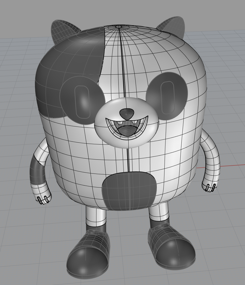
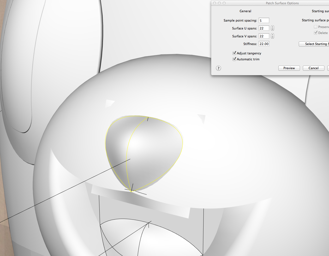
When we started modelling the toy in Rhino we brought in the pictures we needed and traced curves off of them. Afterwards we used the curve network command but found that the resulting surface wasn’t as accurate/clean as we wanted it to be due to inaccuracies in our traced out curves.
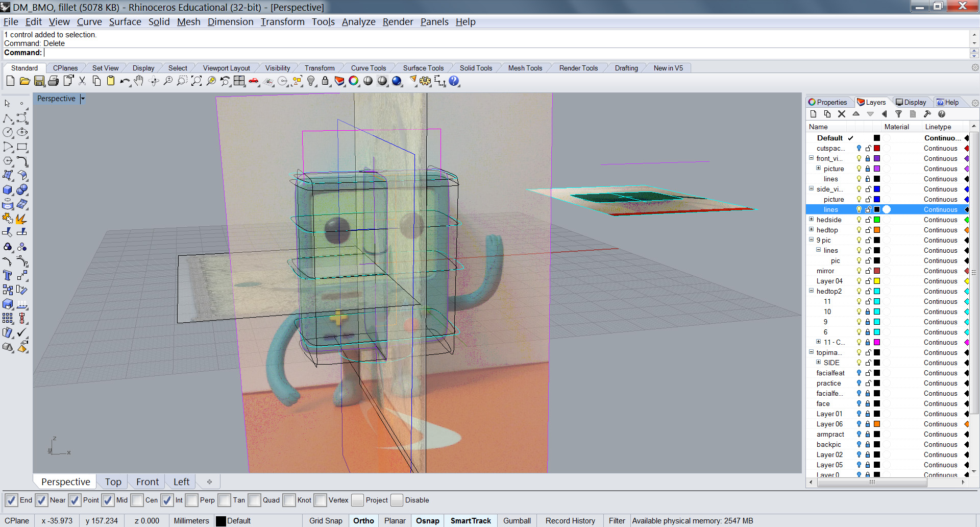
As such, we kept experimenting and eventually found that the strategy of manipulating a cube to match our section images to be a more successful method for our toy.
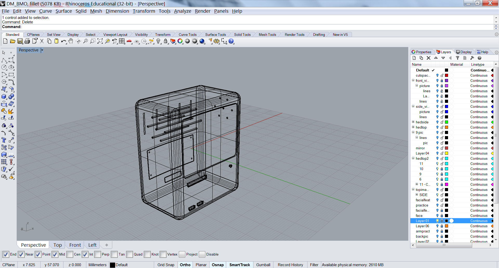
We then added details such as perforations, buttons, eyes, and slots using the extrusion, trim and offset commands.
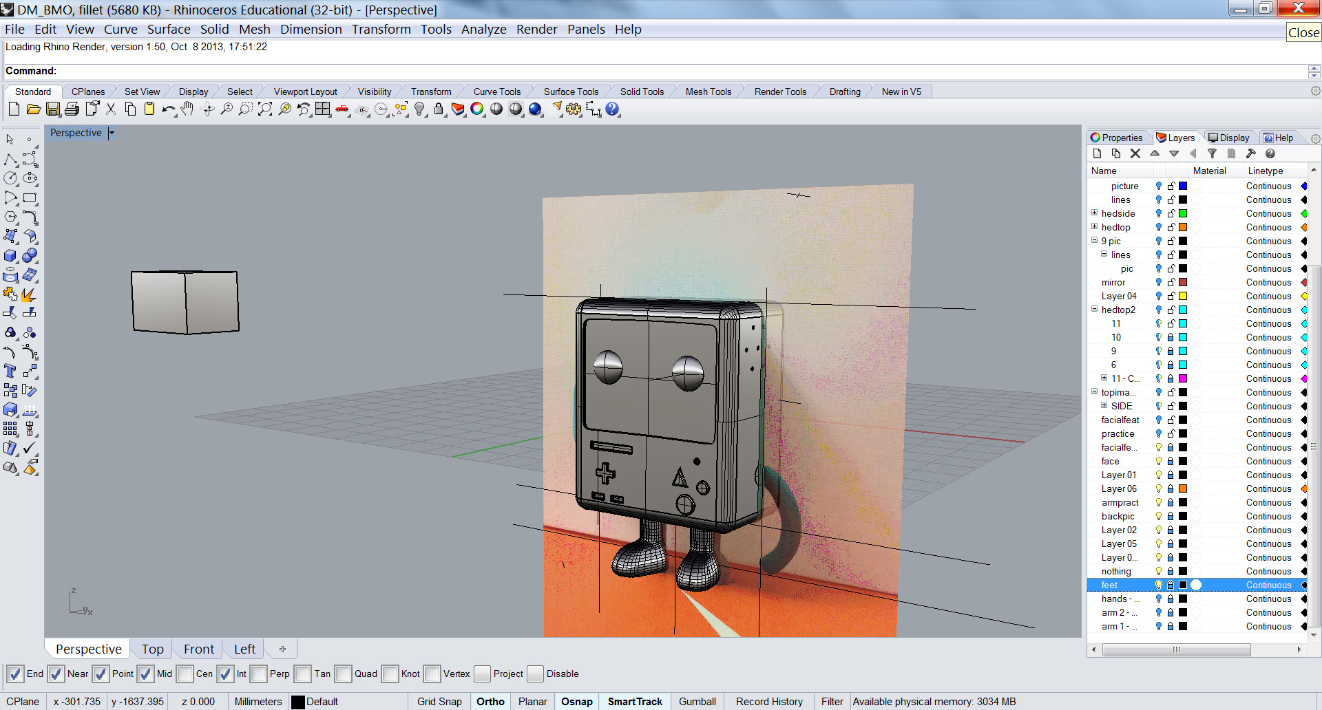
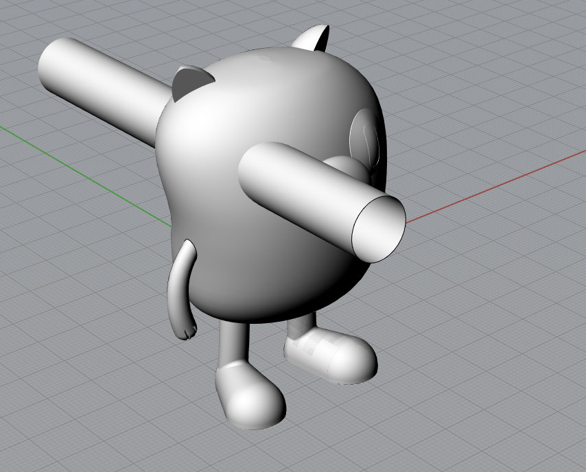
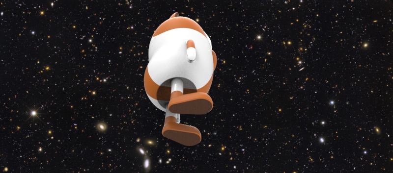
After finishing up the body we moved to the feet of the toy. We modeled these pieces by using curves generated from the front and side views of the toy. We then added curves generated from the horizontal sections to these profiles in order to run the curve network command. Afterwards we fixed some small inaccuracies in the resulting surface using the cage edit command to move the control points around.
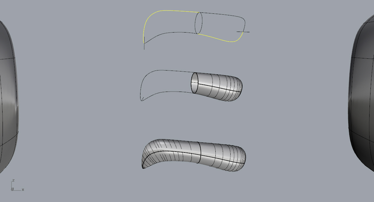
For the arms and fingers we have been experimenting using the rail commands as well as the tube command. Our latest speed bump has been trying to accurately attach the finger components to the arms which we have modeled separately.
After the relatively strait forward and somewhat familiar process of centering, securing, and quartering Walter White came the meat of the assignment; reconstructing Mr. White in virtual space.
The process seemed simple when reviewed in check list form but the intricacies of the assignment became apparent after working on it for just five minutes.
FIRST ATTEMPT
My first strategy was to match up the horizontal and vertical scan sections and attempt to loft from curve to curve and later smooth out the interfaces where the curves met. After the entire structure of curves had been lofted into a primitive surface shape it became apparent that to work with this method any further would be too time consuming and overcomplicated.
SECOND ATTEMPT
Surely a program as advanced as Rhino had a more optimized workflow than I had discovered in my previous attempt. And it did. In conversing with a classmate I was introduced to network surfacing. With this I was able to create more accurate objects in less time and with an average of 6 curves using mostly 2 photographs as my main reference, and the section cuts to a lesser extent.
design media blog post 2design media blog post 2