Category Archives: Uncategorized

Teething out Toothless the Dragon // 1

Toothless is finally beginning to take shape.

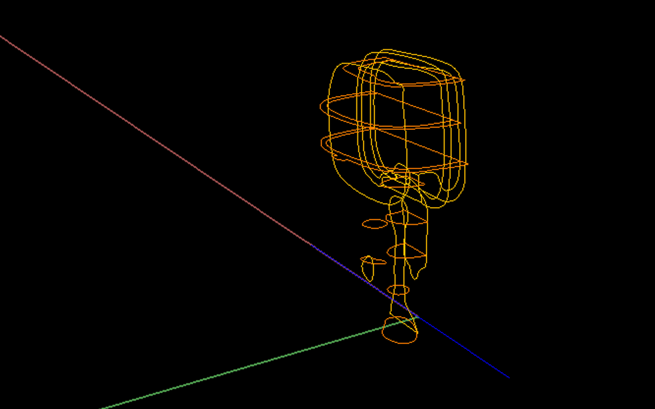
I had a slow start with modelling him because countless (perhaps unnecessary) hours devoted to drawing, assembling, and placing the horizontal and vertical section cuts  in their correct positions: a feature that I, ironically, am not even exercising.

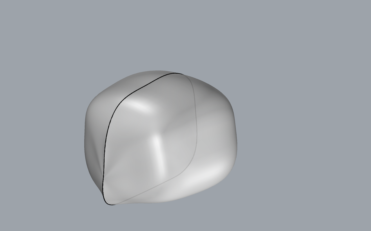
The first component I began modelling was his head. For this, I used one horizontal section, two vertical sections, and one cross section to then run the “NetworkSrf” command between the lines drawn. I then used control points to adjust his face and create his nose, which protrudes slightly out of his face.  I created his eye with a flattened sphere and placed it in the exact same position as the original model.

Screen Shot 2014-10-27 at 11.16.10 PM Screen Shot 2014-10-27 at 11.30.30 PM

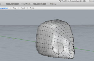
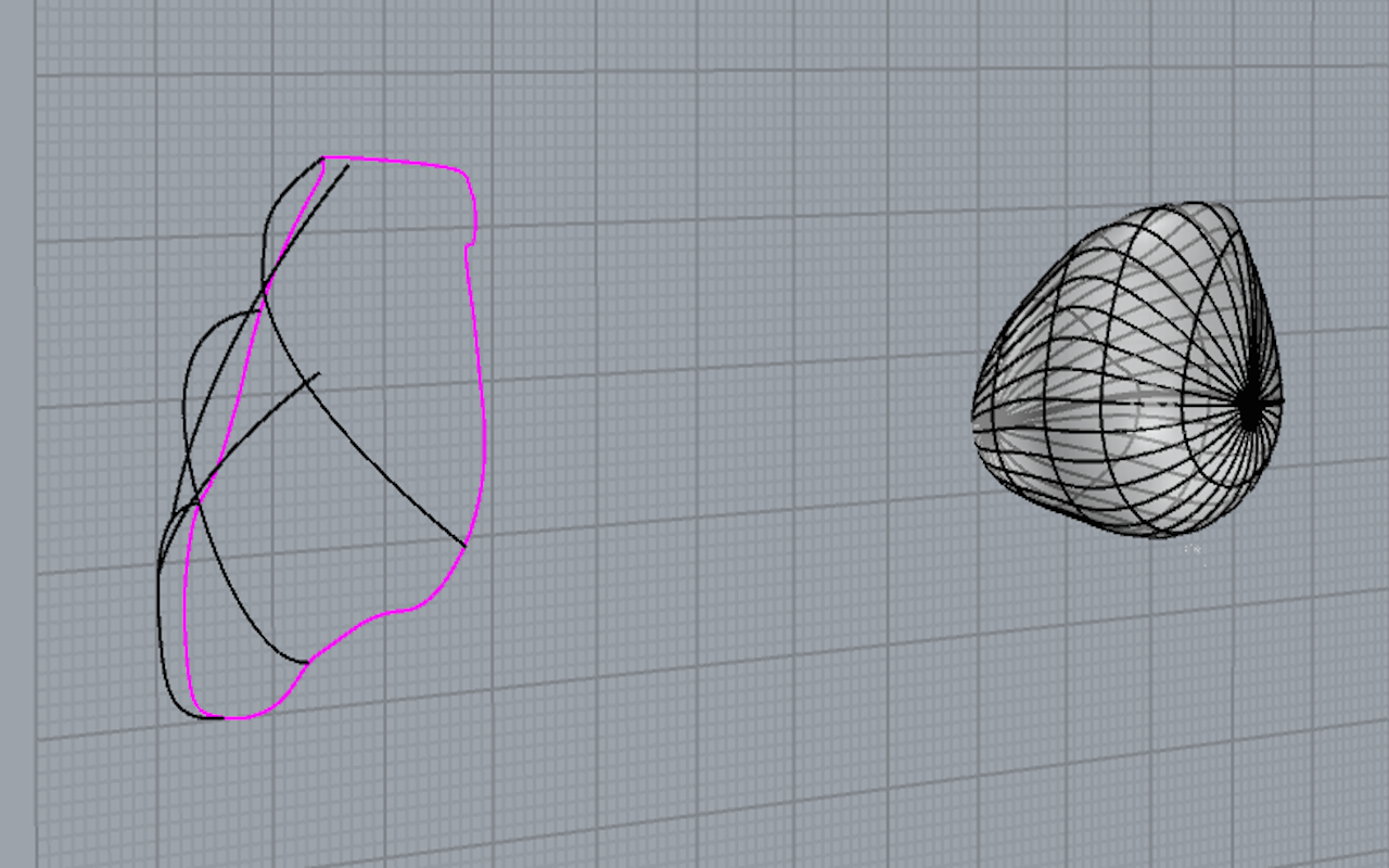
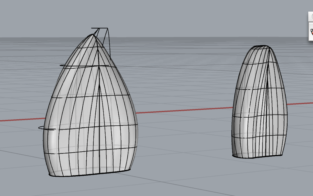
This image represents my two attempts at modelling the body. The “NetworkSrf” command was not successful in using vertical, horizontal and sectional lines for construction in the way that I had arranged them, so I began altering an already made solid, in this case a sphere, with their control points in order to mould a shape that resembles his torso.

Screen Shot 2014-10-27 at 11.14.30 PM

Different strategies for attacking Toothless’ ears were explored.  Much adjusting of control points needed in order to create necessary indentations, curves, and heights.

Screen Shot 2014-10-27 at 11.10.54 PM

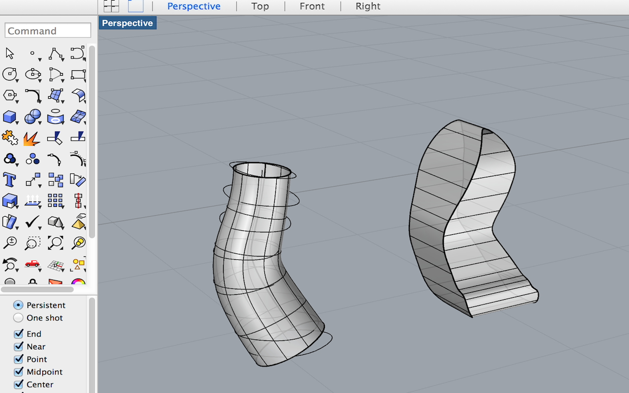
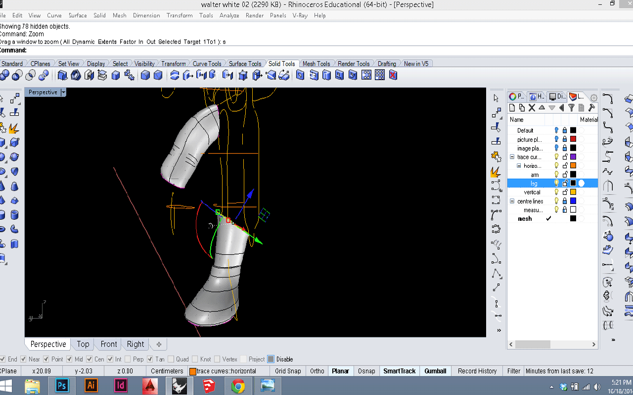
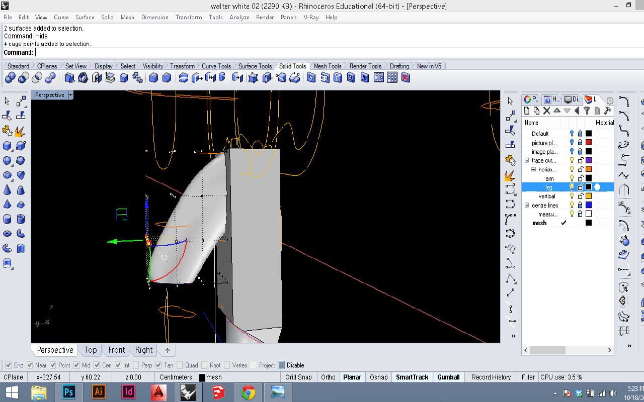
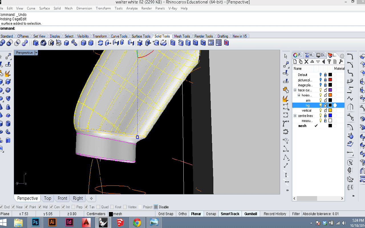
After testing many strategies in constructing Toothless’ legs,  I settled with using the pipe tool. In my next approach, I will proceed to use control points (as few as possible) in order to shape the leg further. I can do this because I created a framework from an earlier, more geometric rendition of Toothless’ leg. This rendition was constructed by extruding one leg’s profile as a surface, generating various rectilinear section lines from the leg, rebuilding the rectilinear lines into circular shapes, likened to the leg, and then constructing a centre curve through each midpoint.

Screen Shot 2014-10-27 at 11.09.15 PM

Modeling – loft, box edits, cylinders and more

This week I took a first stab at modeling. I had my curves from the scanned Walter White segments, plus images of front, back, and side to work with.

My first attempt was to use the curves I had already drawn, plus any extras I thought would be necessary, and loft them into a surface. I spent a full day modeling a leg and arm this way, and although I eventually got the leg right, I never did manage to get the arm looking good. Below you can see the curves in black.

10-18-screenshot01I

I eventually gave up on the curve-loft method. Now I am working with geometric solids, which I boolean to an approximate shape using other basic solids. Then I soften edges using fillet. Finally, I can tweak the object using box edit to get things just right. This process is working much better! Below, you can see a box for the body that I am starting to shape. It’s still very rough. The arm was started as a cylinder, and is ready to have a cuff added.

10-18-screenshot015


The image below shows the process for adding the cuff detail to the arm. I created a smaller cylinder, and scaled and placed it. Then I exploded the cylinder for the arm and the one for the cuff, and used blendsurface to connect them.  The final step was to join and cap the 3 resulting surfaces, so I could fillet the edge at the bottom of the cuff. I’ll be doing roughly the same for the body next. Stay posted!

10-18-screenshot03


The Hulk Attempt #2

With a better idea of how to set our bobble head to create accurate sections, I designed a better method of how to position the head above the body. The goal was to glue the doll to a solid back board so it was securely in place for the spray foam and the band saw. I needed to fill in the gaps that its over size head created between the body and the back board. Then I had to position the head correctly over the body because they are two separate parts after I removed the spring. I accomplished this by layering material beneath and around its body and head and then glued it into place. Then, I enclosed the box and filled it with spray foam. Amy continued the process in the workshop to successful cut accurate sections.

WP_20141015_001

WP_20141015_005

The Making of: building the box and injecting the foam

Last week I proceeded to create a container in which to encase ‘Walter’. In creating this box my prime directives were to execute the process with the utmost precision and to mitigate the potential for error in the live foaming process. To do this I took a number of measures which manifest in the creation of my casting mold.
It struck me that to navigate this assignment with as little risk of complication as possible, it would be necessary to place Walter within the very center of the box in an effort to align the toy with the cutting plane. To do this I found the center of my bottom panel and the center of the interior dimensions of all four sides of the box and marked them off. I then glued Walter to the bottom panel of the box, looking directly down from above, centering his giant head over top of the crosshairs I had drawn previously.
The assembly of the box was executed with consideration that it was to be merely a container for the finished product and would likely be destroyed in the removal of the injection foam Walter brick.
Concluding points
The box was a success and served its purpose as the formwork for the final product. There was a slight hang up where the foam weakly bonded to the box, and in retrospect I would have used a release agent. The Walter brick fits snugly back into the container the original toy came in.
See Tam’s post for the next step in our process!

wally

Tracing scans and placing them in 3d space

 Today I traced the slices of my vinyl Walter White in Rhino. Tracing the contours shown by my sections was relatively straight-forward, although there are a few decisions that I had to make which will likely affect the ease of my future modeling. For one, I had to decide which parts to keep as one curve – should the hair, for example, be drawn as part of the same outline as the head? Since the hair and some other sections are not perfectly symmetrical, I opted to trace those separately, but am still not sure that I made the best choice. The first image below shows tracings of the front to back slices.

The more difficult part of this week’s activity was to arrange each of the sections into 3-d space. After some trial and error, I came up with a method to also trace around the image of the foam block encasing each section. This made it much easier to align each section properly, one on top of the other, by snapping each bottom right corner into place and rotating as needed. As I put each section into place in the top view, I then dragged it the appropriate distance upwards or downwards in the side view. I took good notes of where on the model I took each section, but found that I didn’t account for the width of the bandsaw blade. I’ve averaged out each section (knowing the total length between all of them), but am worried about this lack of precision. I would likely have saved myself much fiddling by accounting for and noting the saw’s kerf. 10-13-screenshot02

10-13-screenshot01