Category Archives: week 6

Learning from Trial and Error

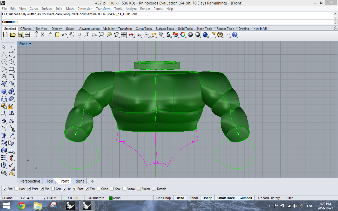
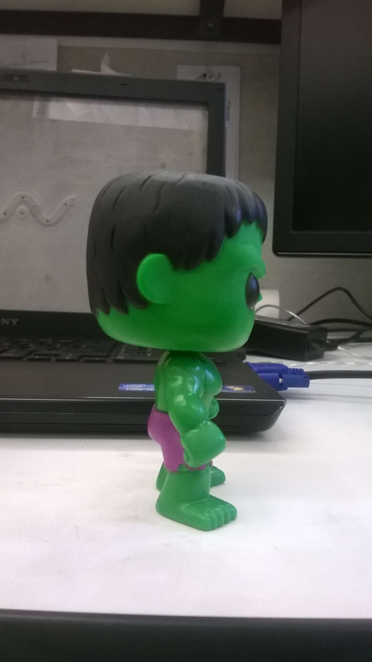
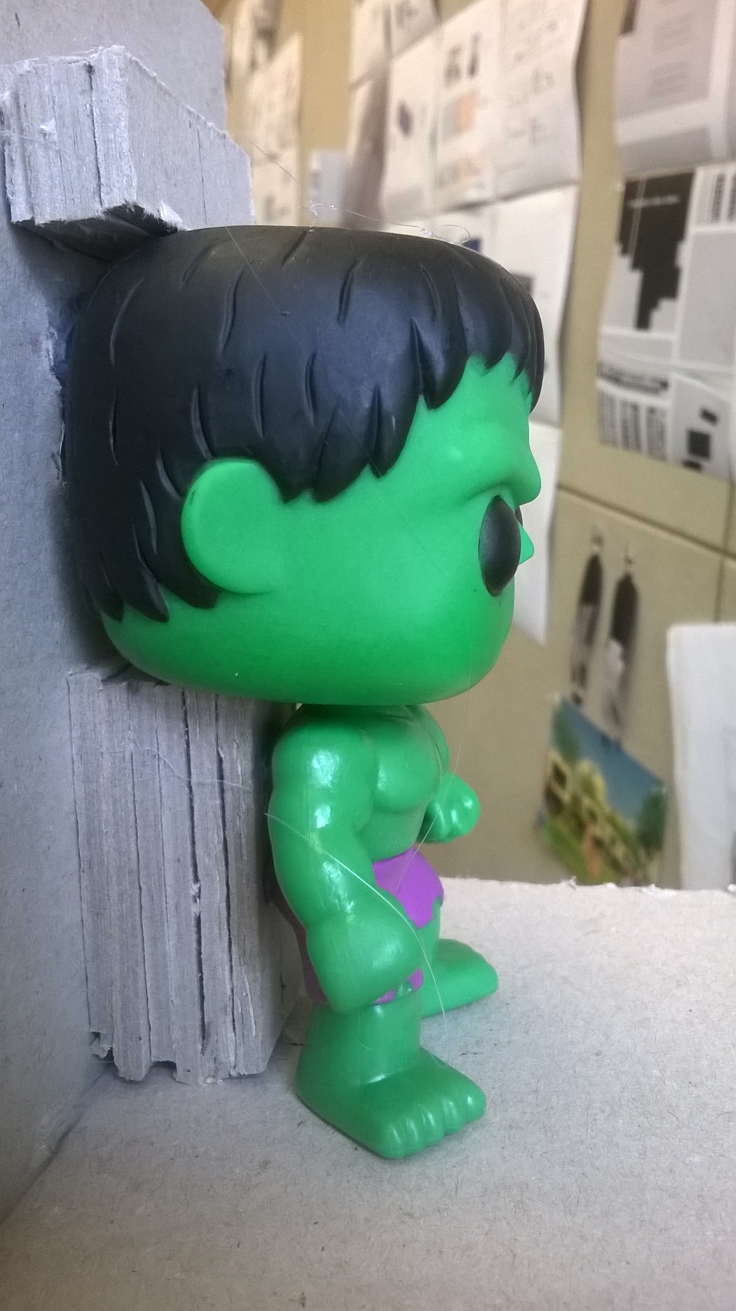
For the first two weeks of this project, I spent my time trying many different things to create the “incredible” Hulk’s body. The most difficult part was creating surfaces with muscular definition, as the hulk is very ripped. In the end, I ended up with a Hulk that I wasn’t happy with and a handful of different torsos, legs, arms and heads that I built using different methods. After realizing this approach was not going to work and observing other peoples’ models, I decided I needed to try using techniques that were much simpler. On the bright side, I learned a lot more about how to use rhino by trying all of these different methods.

First Hulk
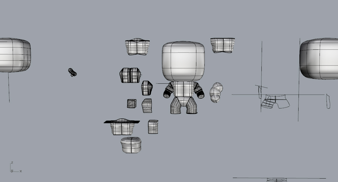
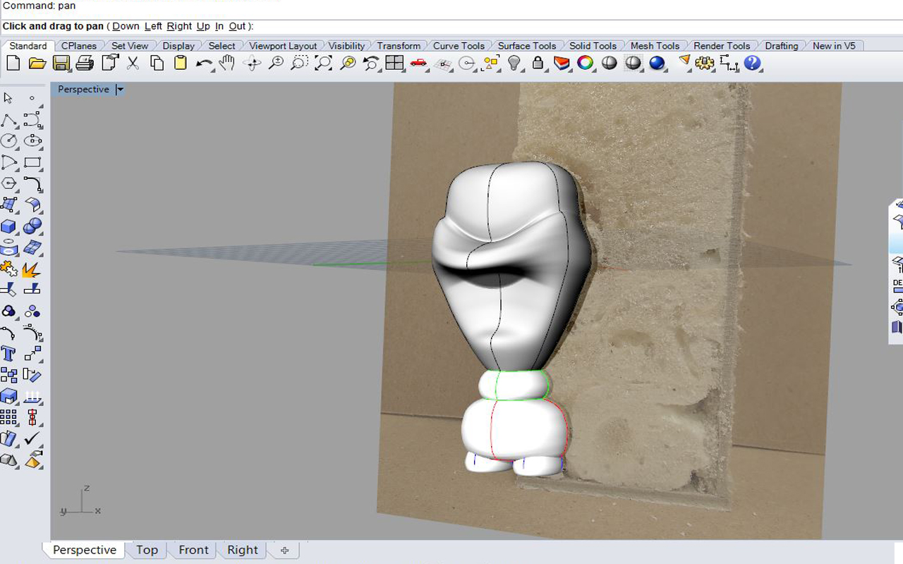
First attempt at the Hulk. Lots of attempts at the chest!

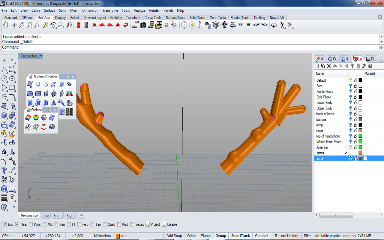
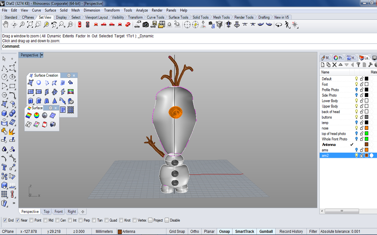
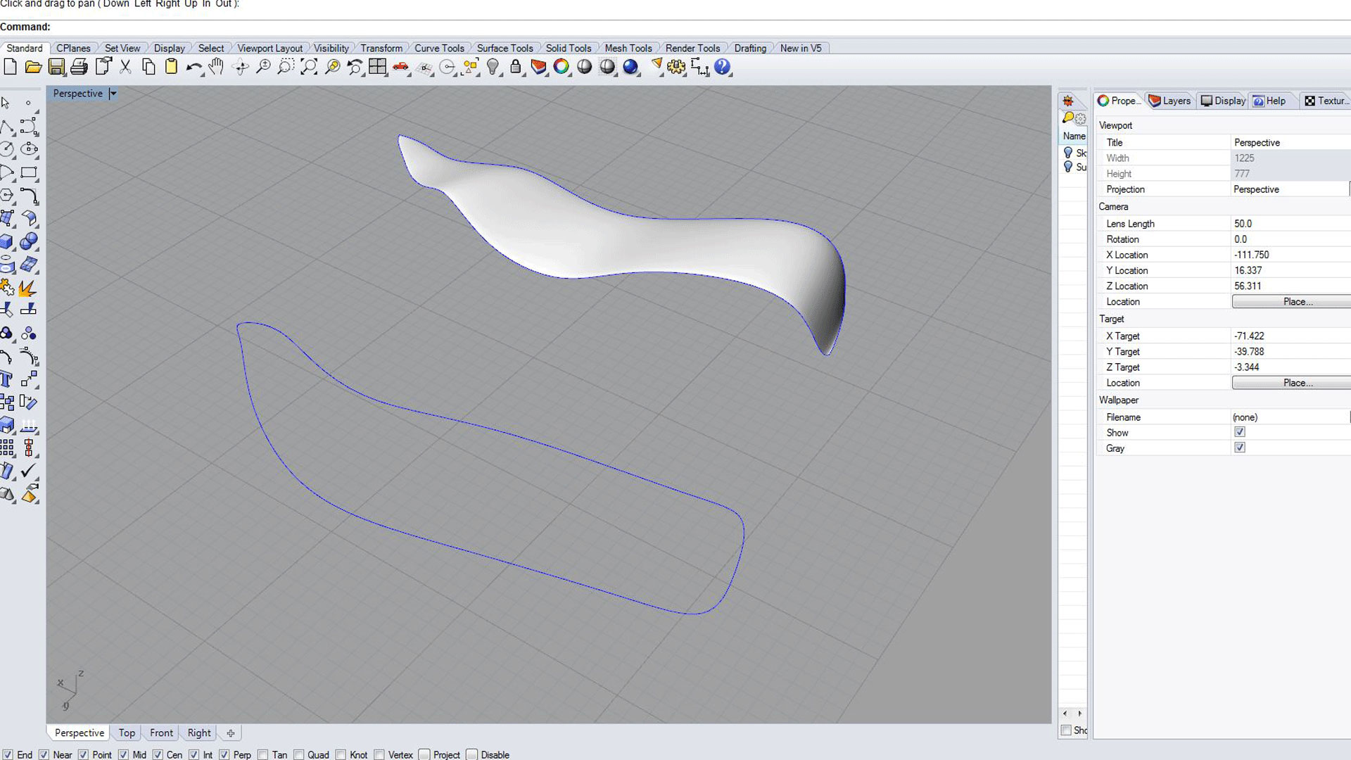
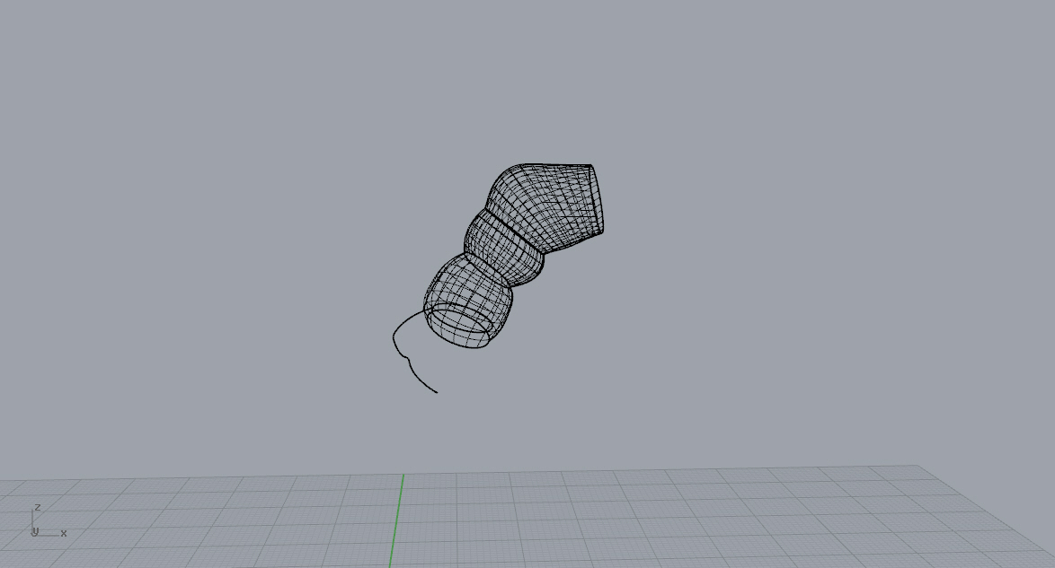
The arms: The first method I tried was putting spheres together. This was an easy method that definitely did not work. I also tried the command “sweep 2” and “rail revolve” to make the individual arm muscles and then I pulled them together. This looked better, but still wasn’t great.

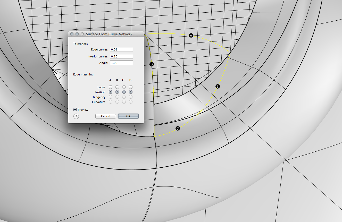
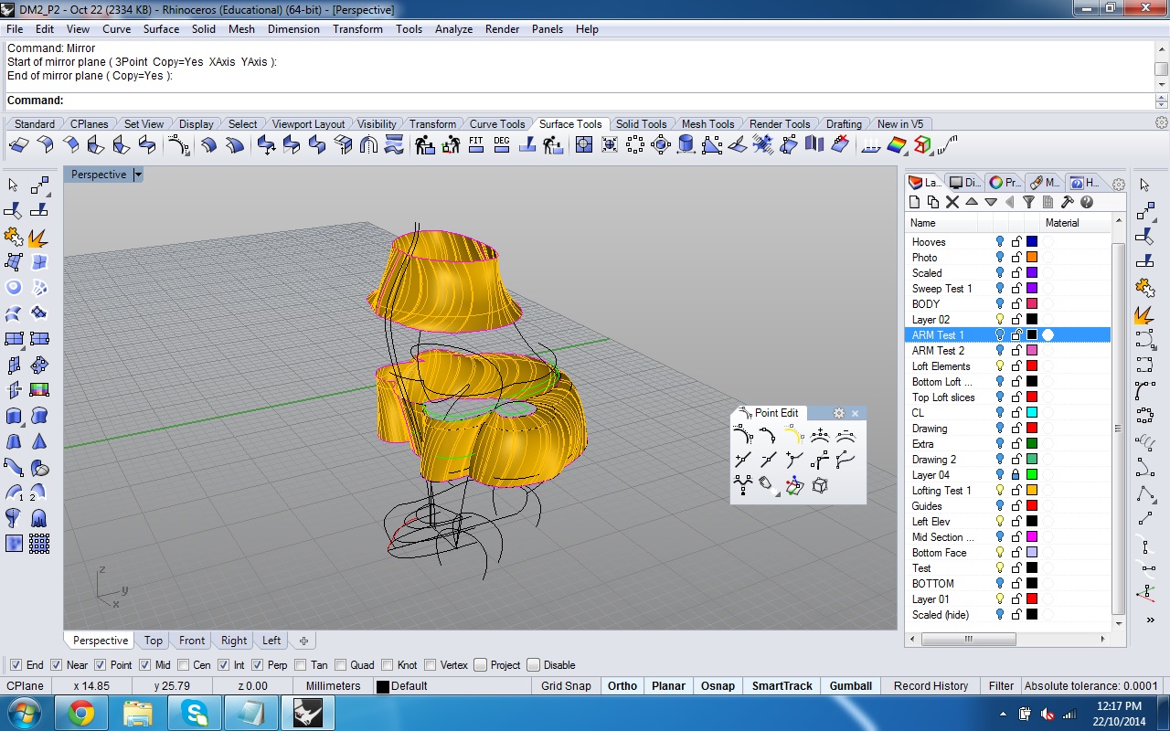
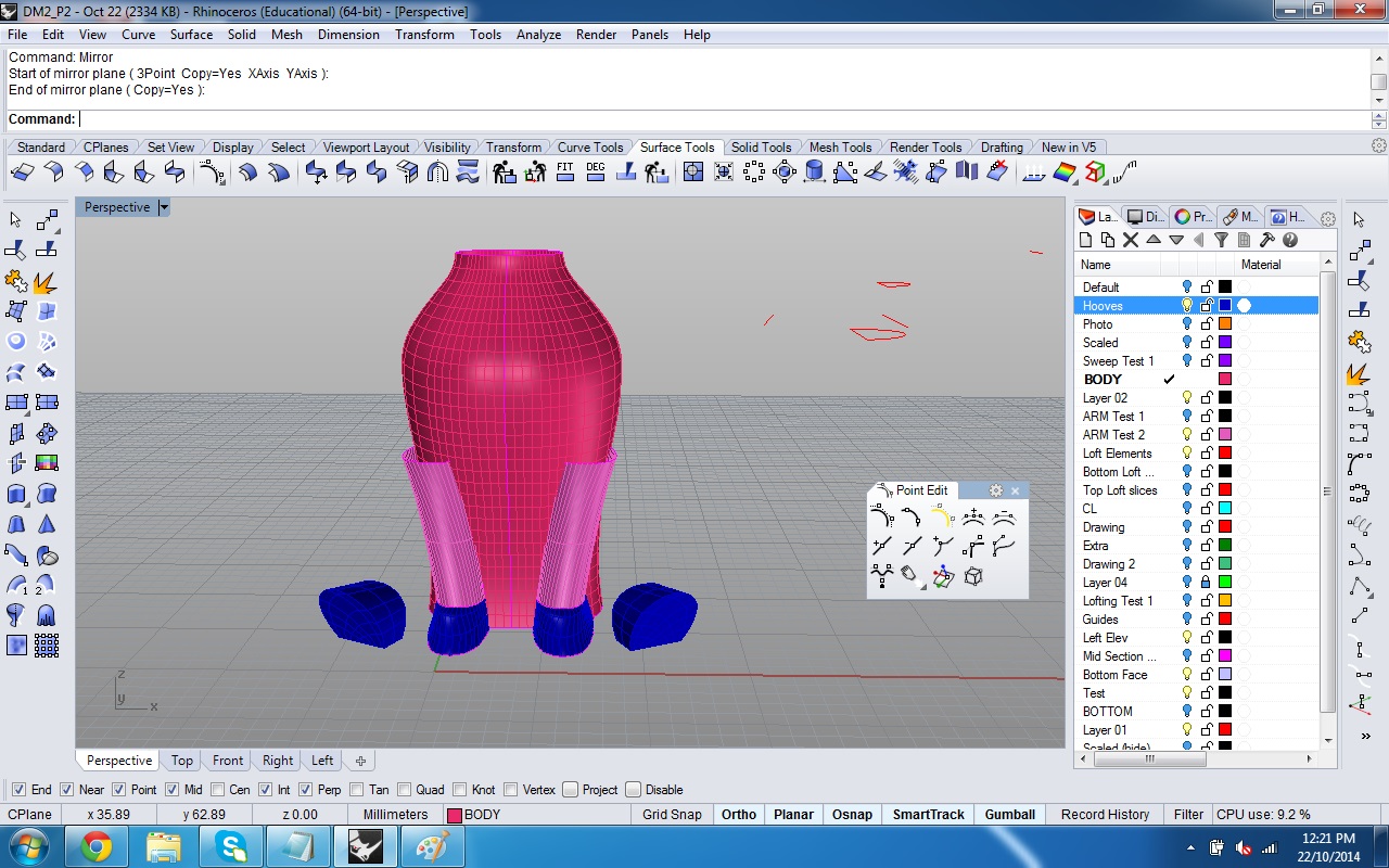
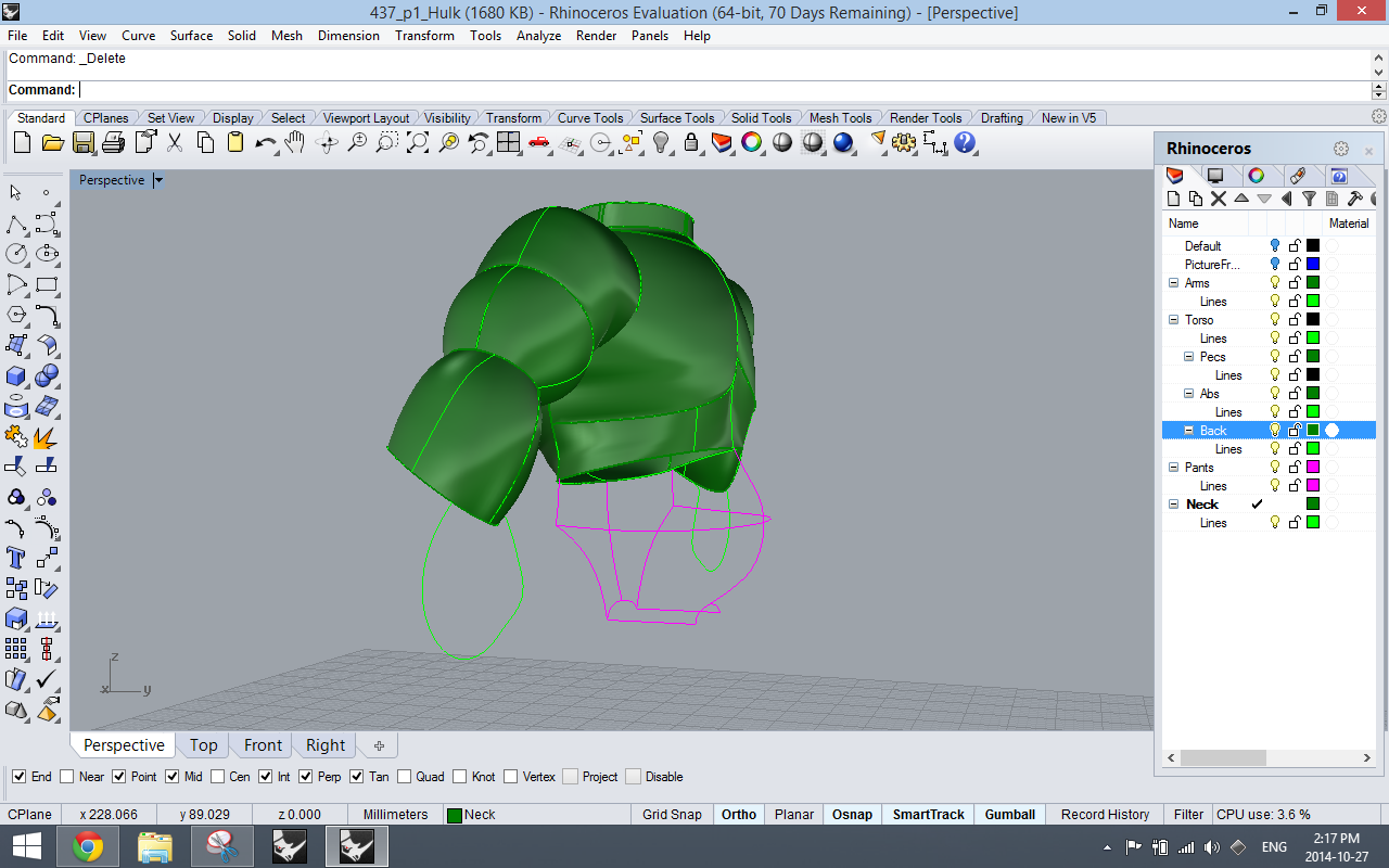
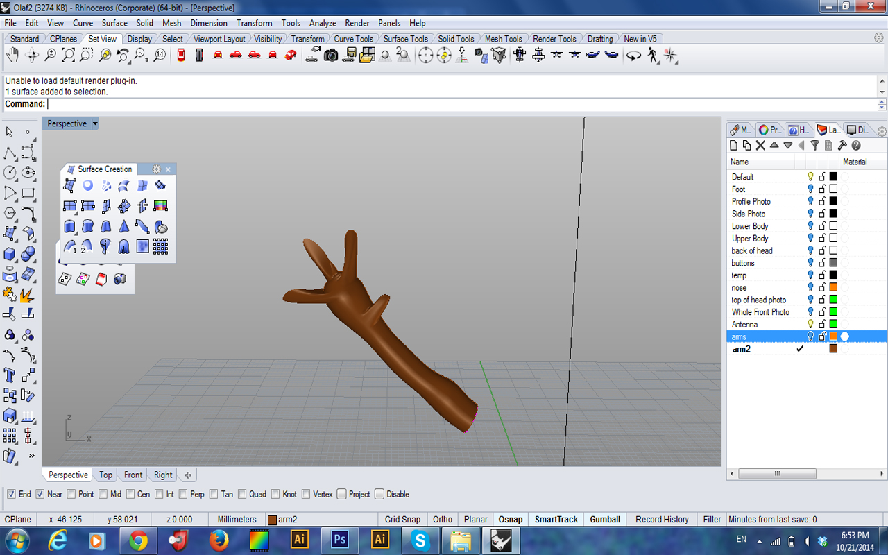
The solution was using curve network surfaces to create each muscle! This created the best result. Using curve networks also ended up being the solution to create the legs. Yay!

Good arm
Curve network arm

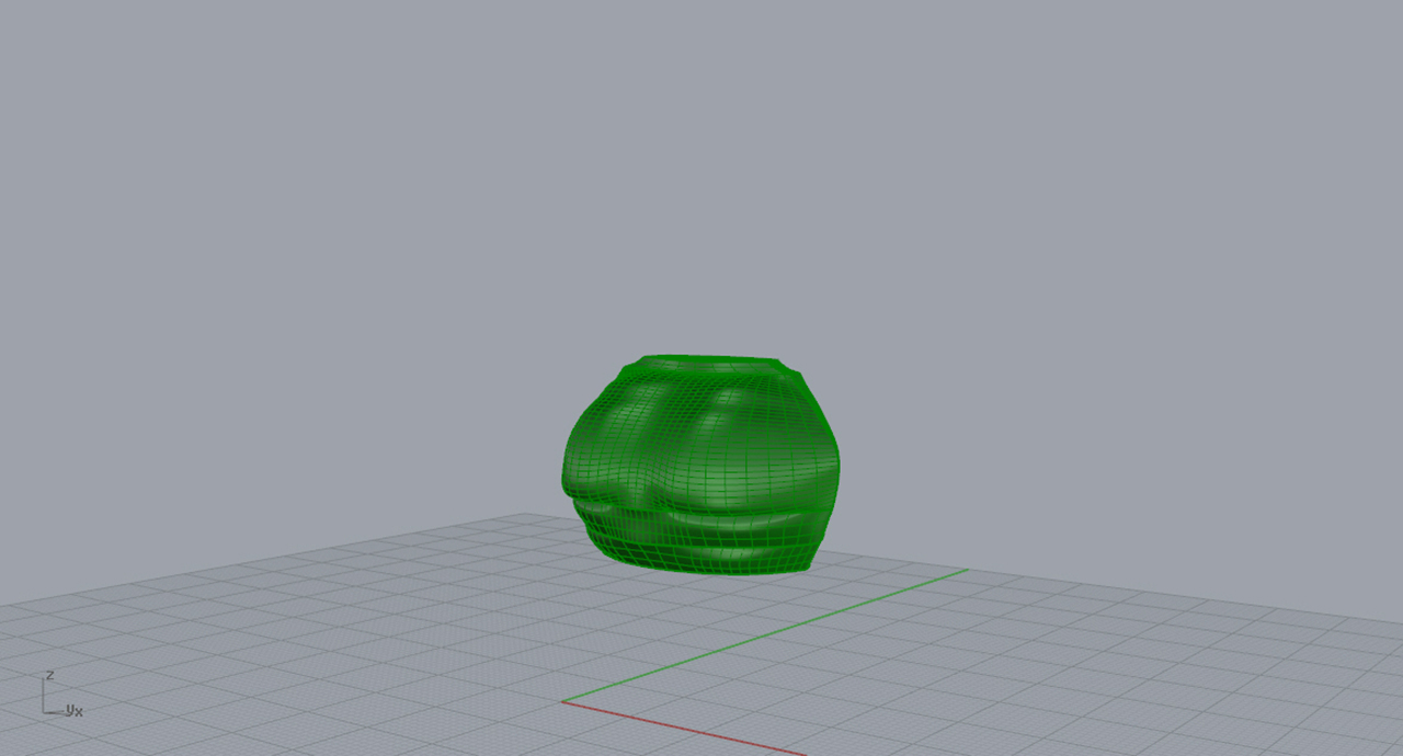
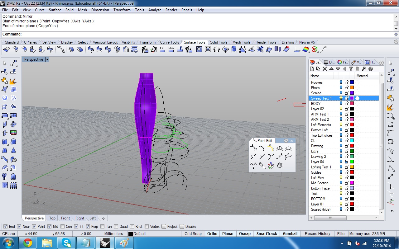
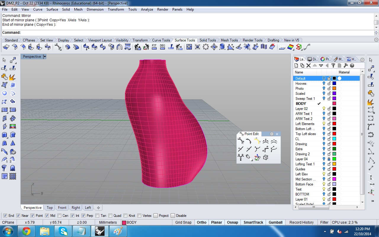
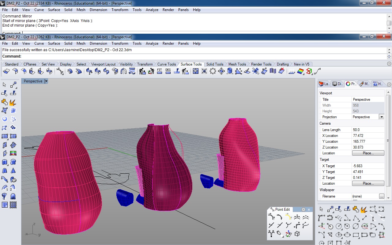
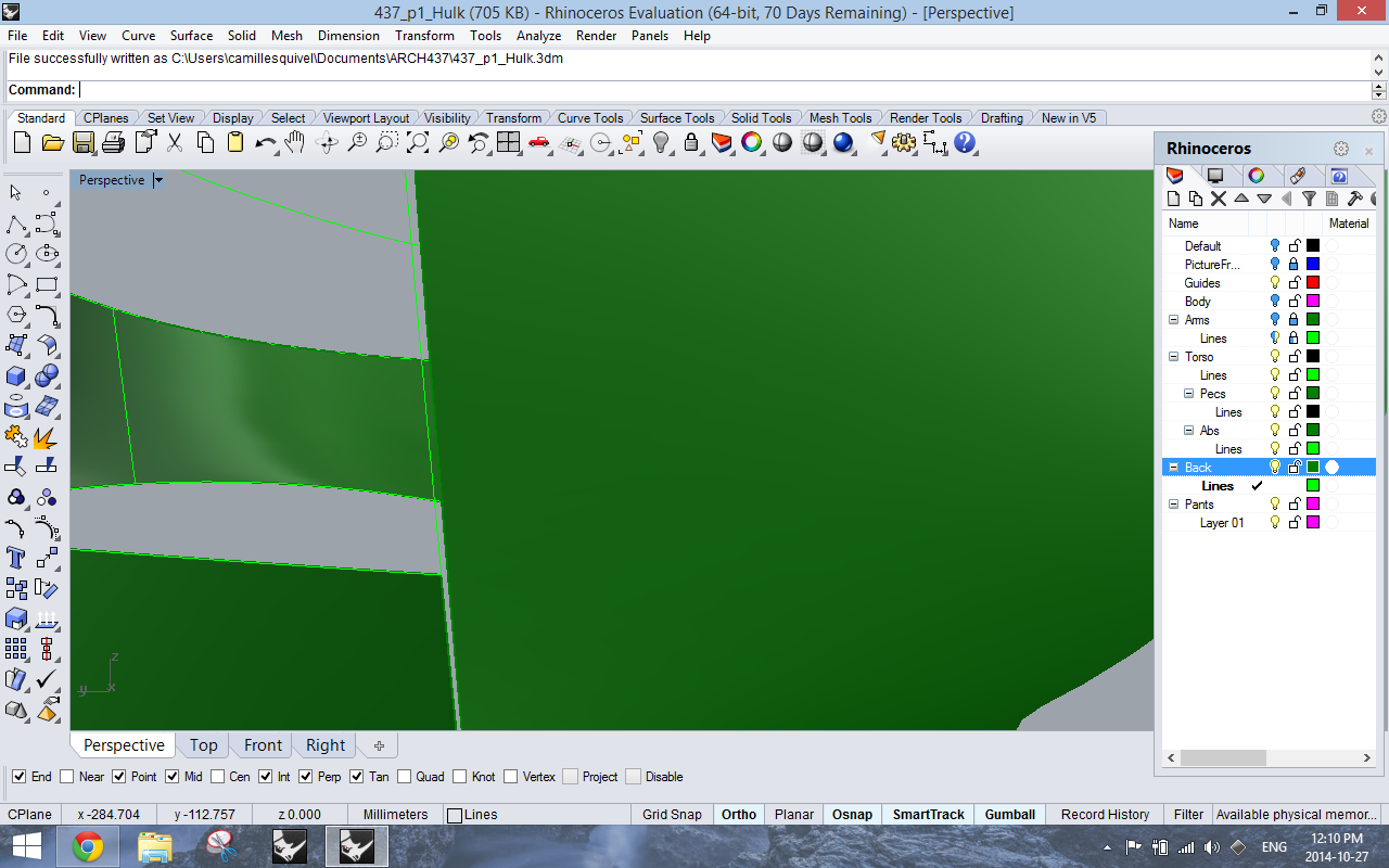
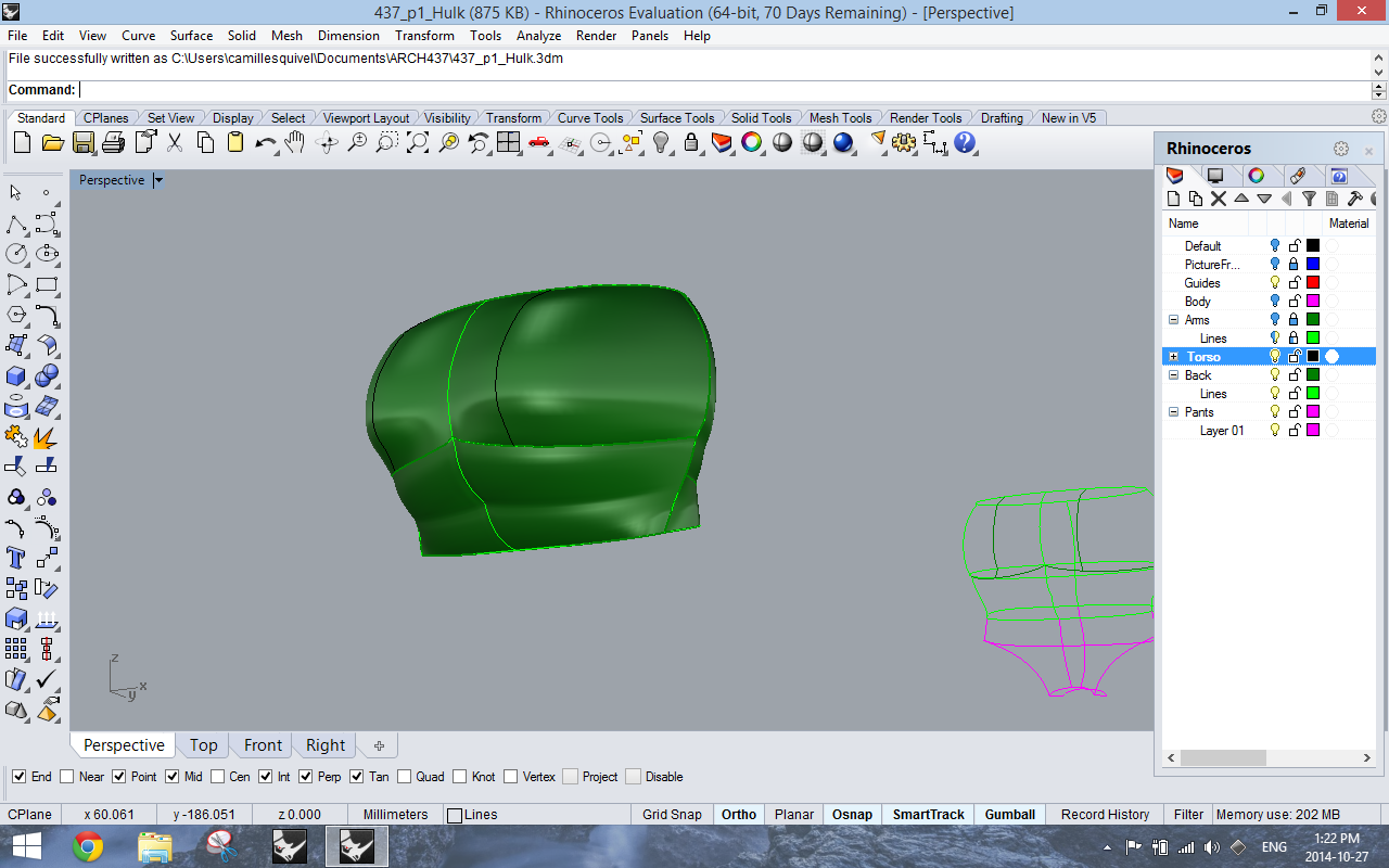
Techniques to building the chest: The first way I tried to build the chest was through lofting vertical lines together. This created a surface that looked “blocky.” Then I thought it might work better if I lofted together horizontal lines. I was wrong. Then I tried using “rail revolve” to create a basic shape and then played with the control points. Once again this did not work. Keara was able to figure out how to make the torso in a way that made the muscles look really good. She used lines that were well positioned to create definition and then created a curve network. I once again learned that taking time to really think about how the lines come together creates a more simple and better result. We now have a beautiful looking chest!
Good chest

WEEK 6 Progress

Leanne- Cake is almost done being modelled minus some work that needs to be done on details and creating closed surfaces. In our last post we were experimenting with creating the shape of the body and in this post I will show how I created the extremities and details (mostly commands such as surface network, ellipsoid by diameter, sphere by diameter, sweep2, boolean union, split, join, and by manipulating control points on objects).


First image

Above is the nearly finished version of Cake.


2nd Image

I started with the arms and eyes. The eyes were simply made with the command “elipsoid by diameter.” I took measurements directly off of the doll and made the elipsoids to this dimension. The arms were made by tracing a photo of the front view of Cake. I traced the arms and compared this with measurements directly from the model. I placed an elipse at the bottom of these two lines and did the Sweep 2 command. I then capped the holes to have closed objects.


3rd Image

Next I attempted the feet. I struggled with this a little bit. First I attempted a method using thenetworksrfc command (the brighter red foot on the right). I traced the shape of the bottomof the shoe off of the model, then created a wire frame of the shoe based off of photos and measurements. It was really hard to accurately measure and I realized I was getting too detailed. I was getting tired and the foot came out really terribly. I decided to try a new method. This was to manipulate control points on an ellipsoid. I manipulated them to match up with the actual footprint of cake and the outcome was much better than the first. I trimmed the new shoe with a plane (as you can see in the photo) and then capped the object.


4th Image

Finally I worked on the nose. It took a few tries to get it right. The first attempt was to manipulate control points on a sphere. The second was to take the profile, use photos and measurements and create a wireframe to run the networksrf command with. This did not work for me. It was too finicky and a waste of time. I ended up going back to manipulating surface points to get a desirable outcome. I did the same with the tip of the nose and have yet to figure out how to join these to objects.


VIK 1

Viktoria – My approach was to combine tools like pipe, surface curve, patch, loft.  I ran into issues in making the fingers – I attempted to pipe separations and then split the difference then fillet to smooth them but the effect was not entirely successful in making the hands accurate to the actual object.  I also had to reconsider some approaches when I considered the rendering requires, so make separate pieces that would be the different colours of the model. To make the face I traced the eye in front view from the photo then extruded through the torso booleaning difference to create a circle that warped to the contours of the torso then making surface curves to create the shape.  I had initially attempted to create the eyes using spheres but found that method inaccurate and harder to control.  I will rework the facial details in my next iteration for further accuracy and fidelity.  This current model is not ready for 3d printing yet as it is not water tight – there are some ‘messy’ bits on the inside that need to be cleaned up and edges that need to be closed.

VIK 2 VIK 3 VIK 4 VIK 5 VIK 6 VIK 7 VIK 8 VIK 9 VIK 10 VIK 11

In playing around with my renderings I had a few different approaches – I used matte paint materials for one model and metal paint materials for another.  The matte version (though more like the actual model) came out looking dull in the render.  The shinier metal paints gave the rendered model more dimensionality and liveliness but is less true to the actual model.  I also realized in rendering that I am missing an orange arm patch on one arm, and that the back of the mouth/throat needs to be separated in my Rhino model so that I can colour it separately

lVIKTORIA RENDER 1VIKTORIA RENDER 2 VIKTORIA RENDER 3 VIKTORIA RENDER 4

Finn: Adding Surfaces

This week I gained a lot of practice with three aspects of digital modeling. The first was learning how to decide when to sculpt my form with control points and when to create more defined edges using boolean union. One challenge I came across that helped me understand the usefulness of control points was learning that our toy itself is so fragile that it caved in on itself during the slicing process and as a result, gave some inaccurate curves that needed to be eyeballed during the tracing process. I used control points with the o-snap on ‘point’ and ‘perpendicular’ to make sure that horizontal and vertical lines cmd in contact with each other so that the wireframe model aligned.

Documentation5

The boolean union command came up when it was time to attach the ears. I noticed that the ears on my model have a very defined edge at the head and I wanted this to happen in my 3D model as well. The second command I learned to master this week was rail revolve. I sculpted both the head and the ears using rail revolve and joined them using boolean union.

documentation6

Documentation7

The final command I mastered this week was ‘project’. In order to sculpt the face, I projected the curves of the face onto the rail revolved head and created a variety of surfaces to form the teeth, tongue, lips and face. I used revolve to create eyes. In order to make these edges a bit smoother, I used the fillet edge command on each of the edges of the facial features.  Unfortunately, due to problems with the fillet tool, I experienced a series of small holes in the face of my model. I experimented with making a mesh and filling the holes. This experiment was successful in closing the gaps and forming a solid, but created a ‘disco ball’ effect on my model, creating a series of flat surfaces rather than a smooth continuous surface. My current goal is to troubleshoot this issue and move on to the arms, legs, feet and backpack.

documentation4

Bambi Part 2

Modelling Bambi this week involved a lot of testing of various commands and methods. Throughout the week, Vivian and I spent most of our time testing and using the following commands to create surfaces: Sweep1, Sweep2, Curve Network, Loft, Edge Surface and Rail Revolve.

As mentioned in our last blog post, we started to build Bambi’s head by tracing and then “sweeping” in sections, hoping to get around the entire head piece by piece. However, that method led to many undesired bumps and rough edges that did not contribute to demonstrate the toy’s smooth surfaces.

After several tests using different commands, Vivian and I found that “Curve Network” gave the best result, resolving the issues of bumps and properly represented the sphere-like quality to Bambi’s head (see screenshot 1).

DM2_p2_Oct22_2

In addition, we decided that we want to allow the models’ head to rotate (see screenshot 2). We used “Revolve” to create a small nob embedded underneath Bambi’s head, with a gap of 1mm all around.

DM2_p2_Oct22_1

Bambi’s torso underwent much iteration. Screenshot 3 shows parts of the torso using “Loft”. We liked this method because it formed the arms, knees and body in one piece. The problem arose while attempting to loft the entire torso; surfaces disorderly bounced off of curves and jagged edges formed.

DM2_P2 - Oct 21 1000pm

Screenshot 4 shows a piece-by-piece attempt in resolving the torso. Vivian and I used “Sweep2” to create Bambi’s front and back. This was successful, however could not carry forward to the rest of the torso as smoothly as this portion, such as the knees or the arms.

DM2_P2 - Oct 21 1200am

A third attempt involved using “Curve Network”, where several lines had to be added in order to provide adequate direction (see screenshot 5). Some of these lines had to be estimated and adjusted from reference images. The resulting model looked good. Nevertheless, after mirror-ing the second half, the shape did not resemble Bambi.

DM2_P2 - Oct 22 1130pm

Lastly, a final method landed us in a good position for creating Bambi’s torso. Using the model formed by a combination of methods all of the above (ie. “Sweep2”, “Curve Network” and “Loft”), we used a command that extracted curves in specific vertical increments. By adjusting each of those curves to smooth the edges produced in the third attempt, we were able to obtain the model shown in Screenshot 6.

DM2_P2 - Oct 22 300pm

Vivian and I then continued to build the arms and hooves, with commands mentioned above including “Edge Surface”. These parts were not as complex as the main portion of the torso. Nonetheless, we are still stuck on closing off the top part of the arms.

DM2_P2 - Oct 22 1230pm

As we continued to trace our sliced model images to obtain Bambi’s form, these traces became references more than the actual curves used to build the model.

Magic School bus

Next we took the scanned images of the bus into Rhino and began tracing the outline of the sections to create a wireframe of the toy. However upon doing this, we realized that there were a lot of errors and inaccuracies in this method because of the low quality resolution of the scanner.
1

Hence, we started measuring the dismantled parts and modeling them directly in rhino. This in turn allowed us to be more precious and understand the shapes of the toy better.

2

BUS-10-19

Hulk: Chest

6

This week I started to learn about the downfalls of certain commands such as the averaging that Curve Network does but started to learn how to mitigate them with other tools.

7 8 9

This week was spent more setting up lines but began to realize Curve Network was not going to solve all my problems.  Other tools I began experimenting with were: Rail Revolve, Sweep 1 and Sweep 2. Although I know many other students lofted lots of parts for their project… I generally avoided the tool as Hulk’s individual parts weren’t exactly symmetrical.

My generally strategy for creating him was simplifying his parts instead of trying to model large pieces. I’d model the bicep, abs, chest, parts of the back separately for example instead of attempting to create the whole torso or the arm through one command.

Cyborg part 1

Daozhen and I started this project by gluing our toy within a cardboard box and filling it with foam.  We then marked off sections on the outside of the box which were later cut on a bandsaw.

blog1

The next step we took was to scan these sections and place them in Rhino.  We then organized these sections images along with front and side photos of the toy.  After doing so, we traced the sections using curves.

blog2

Currently I have been experimenting with the “surface from curve network” and “loft” commands to generate surfaces but have not been successful in creating very accurate surfaces.

I hope to iron out these issues by continuing to work with these commands and possibly make additional cuts to the toy.

Olaf Part 2

Darcy Keester + Luis Puente

This past week we have tried to model all of the components of Olaf. We first worked on the body last week before realizing our photographs were not very accurate, so we scanned our pieces instead and re-modeled the body. Next we worked on some of the smaller details like the hairs, nose, and buttons (screenshots 1 and 4). Those were done using the sweep and loft commands. We also worked on the arms, which have turned out to be very tricky. Our first attempt used sweep to make the arm and then another sweep to make each finger, which as you can see from the screenshot (#2) below turned out looking not so great. In our next attempt we used only one sweep to get the arm then played with the control points to make each finger (screenshot 3). The trickiest part now is modelling his face. We made a first attempt, as seen below (screenshot 5), using a curve network with curves on the front, two sides, and two in between on his face. However, we decided we need more cuts to our model to more accurately make this part. So we are going to try two different methods of cutting it, since we already have scans of our cuts we figure we can  do that to see which one works better. One method will be similar to the idea of getting those curves down his face, like our first attempt, and the other will be to make horizontal cuts along his head. Besides that our next step is to figure out how to put each piece together and how to make it “solid” so it can be printed.

Olaf_hairnosehead Olaf_arm1 Olaf_arm2 Olaf_almostwhole Olaf_face

The Hulk Attempt #2

With a better idea of how to set our bobble head to create accurate sections, I designed a better method of how to position the head above the body. The goal was to glue the doll to a solid back board so it was securely in place for the spray foam and the band saw. I needed to fill in the gaps that its over size head created between the body and the back board. Then I had to position the head correctly over the body because they are two separate parts after I removed the spring. I accomplished this by layering material beneath and around its body and head and then glued it into place. Then, I enclosed the box and filled it with spray foam. Amy continued the process in the workshop to successful cut accurate sections.

WP_20141015_001

WP_20141015_005

“Zero” Progress

kara to-post---pouring-resin


My partner Bianca and I chose the toy Zero, the little ghost dog from  the Nightmare Before Christmas. We thought that he had enough complexity to require a good range of techniques to replicate, but not too complicated to make our lives miserable. We chose to cast him into resin instead of the spray foam,  to get a more consistent and clean finished product. To cast him into resin, we made a small box out of acrylic that was just large enough for Zero to fit inside without touching any edges, but as small as possible to avoid wasting resin. We cast the resin in layers, pouring one layer before inserting the toy to get a base of resin underneath it. In the future, I would place the toy first. We thought that we would be able to get him to sit at the proper angle, but as the resin cured he shifted slightly off centre. The resin casting took about 5 hours, we found that the ambient temperature had a large effect. It was too cold for the resin to cure if we left it outside.

After 24 hours the resin was set, but it was still tacky to the touch. We left it for another couple of days before cutting it. We weren’t sure about how the cutting would go (whether we would be allowed to in the woodshop), but it was a very smooth process. Using the bandsaw, we first did a test cut to check how the resin held up, before cutting into the toy in two places.

kara to-post---just-cut

cut-pieces


We made one cut in section view, and one cut in plan view. The horizontal cut gives us information about the depth of the eye, which was one of the only things we couldn’t get from the intact toy.

My first forays into modelling were based on photographs of the intact toy. We set up a black background and took the most accurate photos we could orthographically. I centred these photos and made them consistent between the views, then set them up in Rhino to work from.

kara to-post---first-workspace

I attempted to model the head of the toy using a filletedge function, to see how close I could get just eyeballing and to test out modelling the shape. It’s not quite right, so I will be using information from my cast pieces that I will scan to be able to use a rail revolve function. kara to-post---ear-trial

This is a test model of the toy’s ear that I made using a sweep2 function. I started with the shape of the ear from the top view, then broke the shape up into 3 discrete curves. The two side curves became the rails, and the short curve that attaches to his head became the curve that sweeps between them. I turned on the control points to adjust the curvature in the Z-axis, while maintaining the points where the curves meet. I used the sweep2 function and got the surface for the top of the ear. I will continue the shape by creating the bottom surface of the ear, and then lofting between the two to make it an actual shape. I will fillet the edges to soften them, and then attach the ears to the toys’ head.