Category Archives: week 7

Finishing Bambi Model and 3D Printing

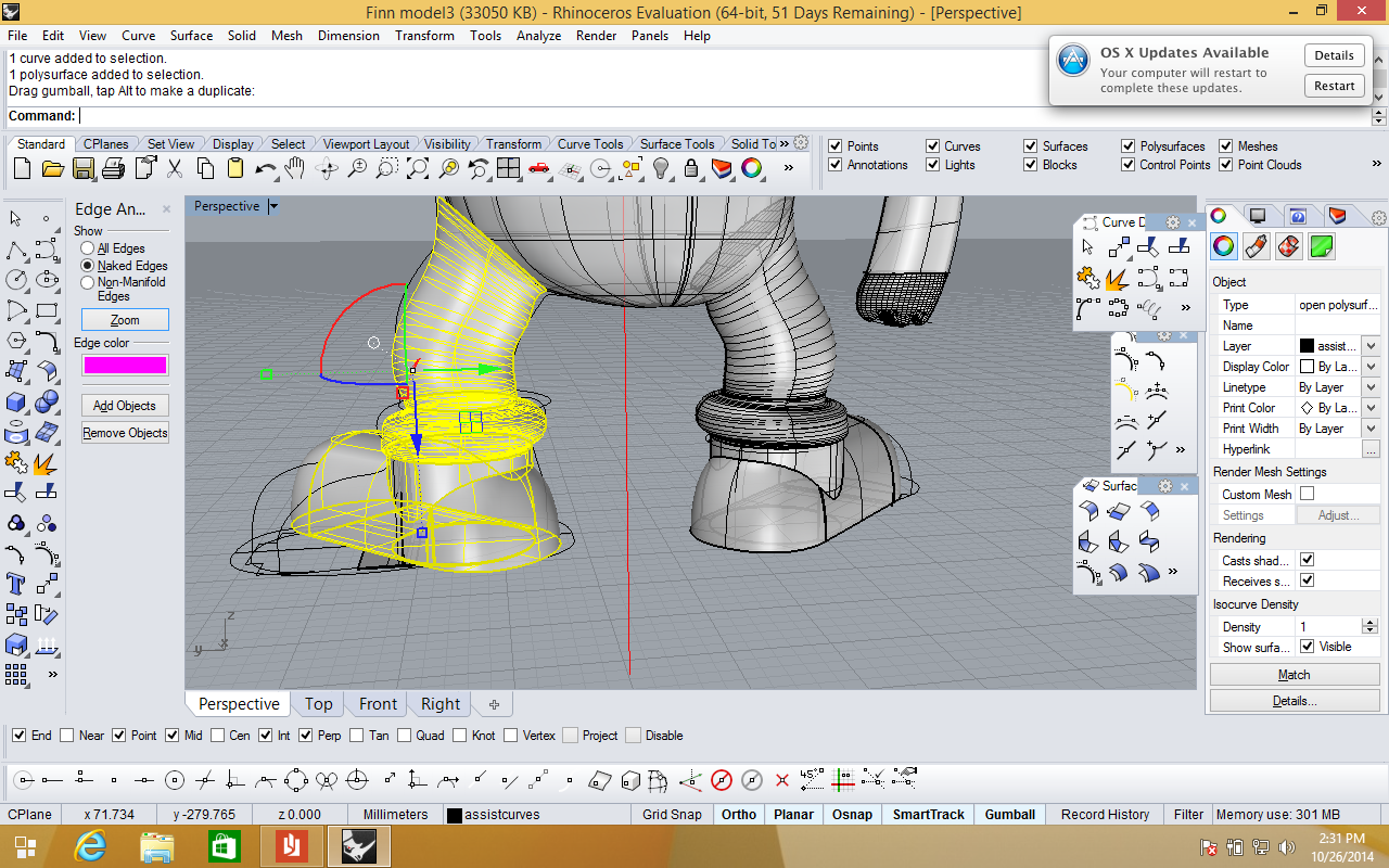
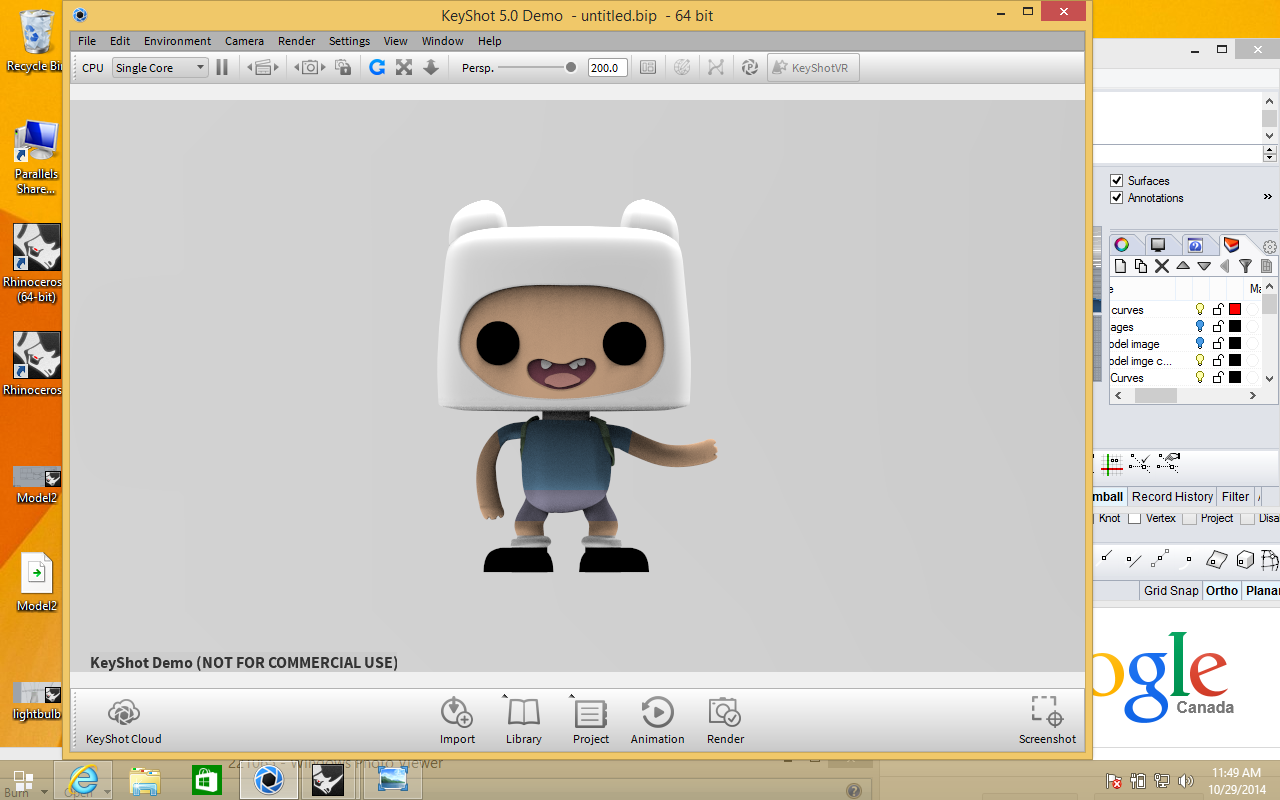
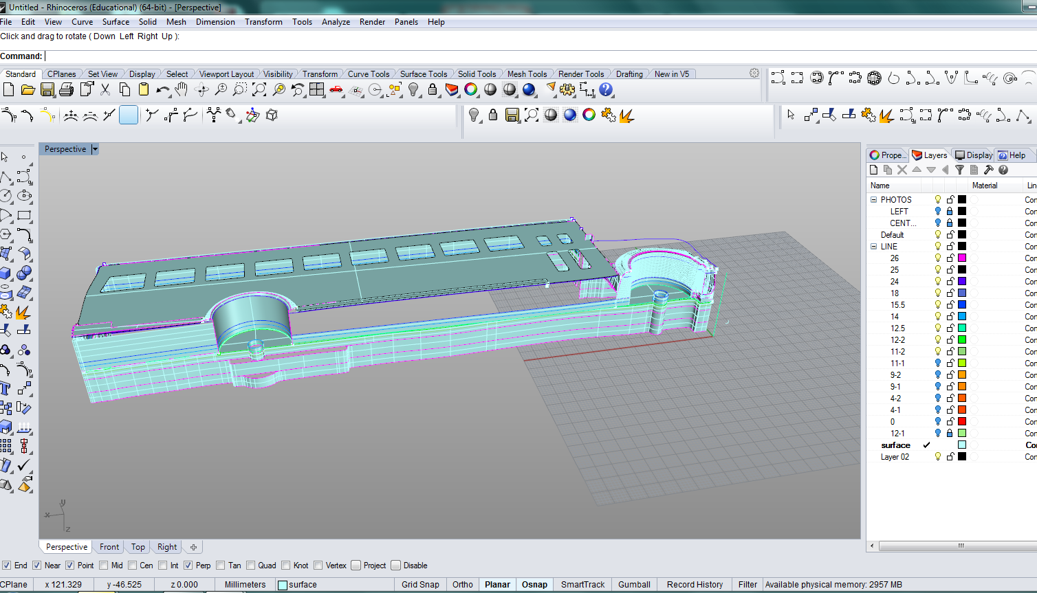
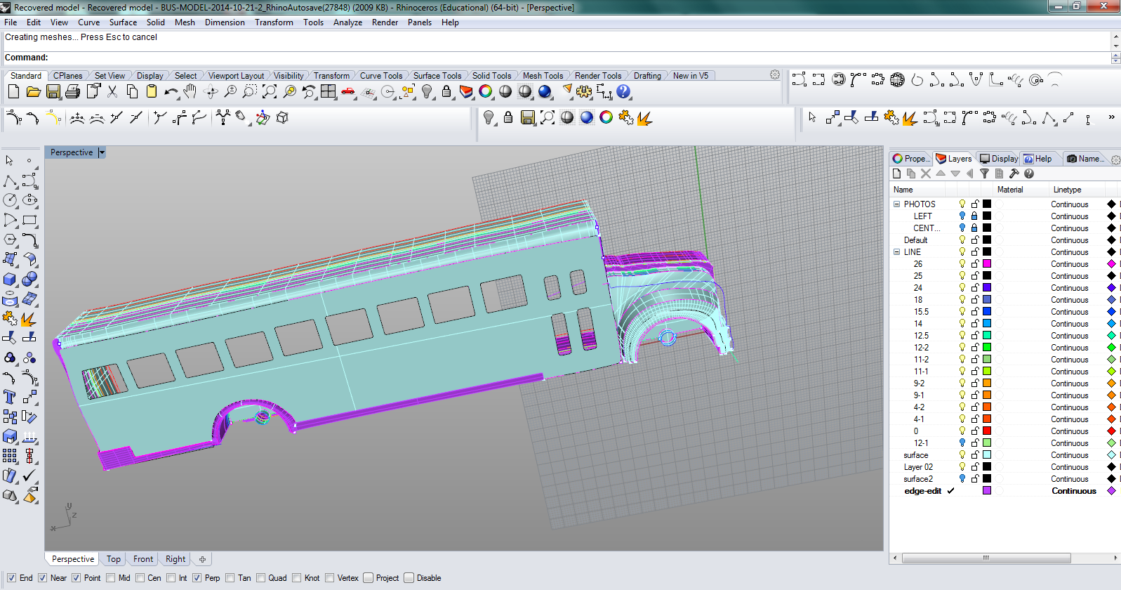
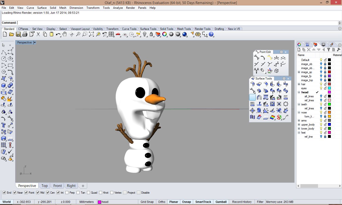
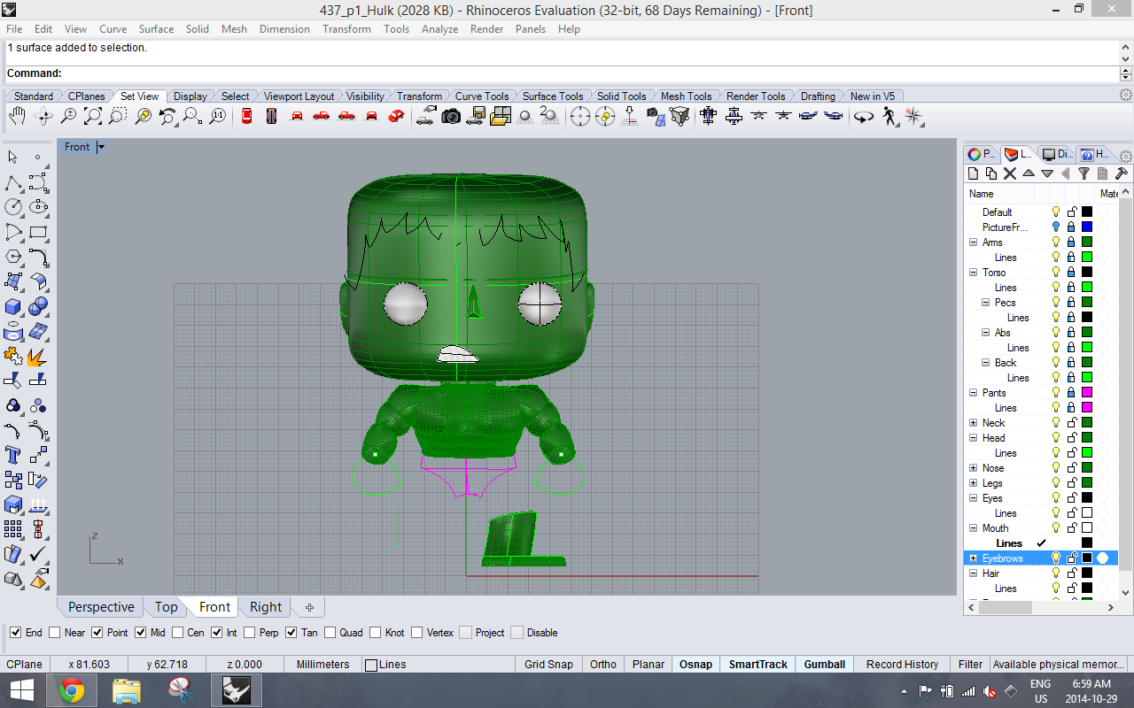
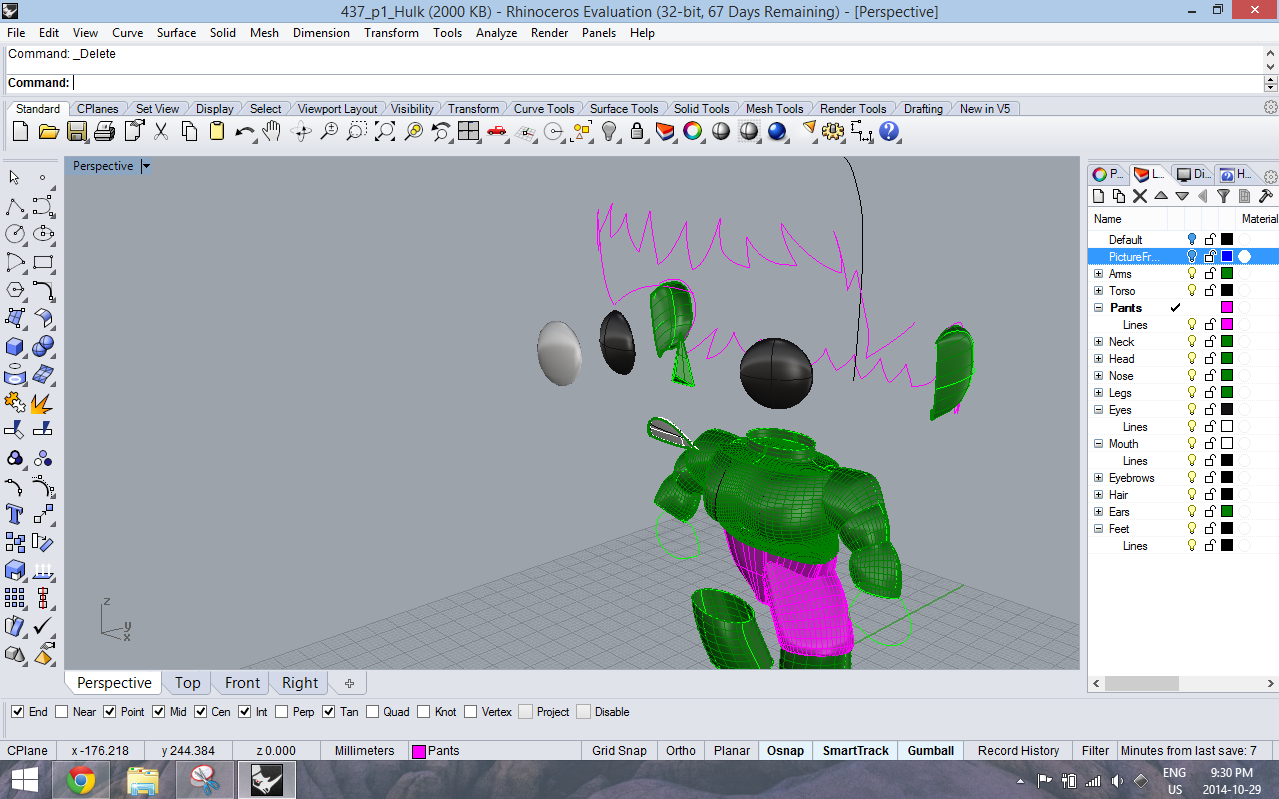
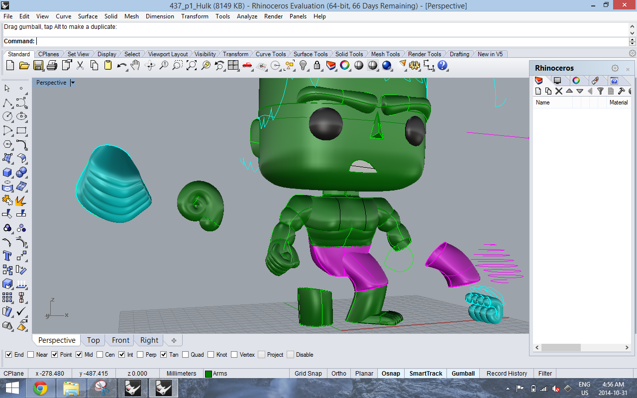
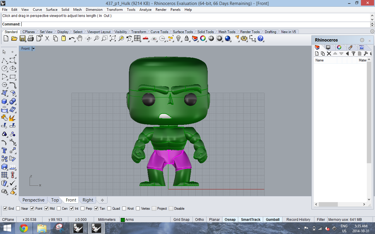
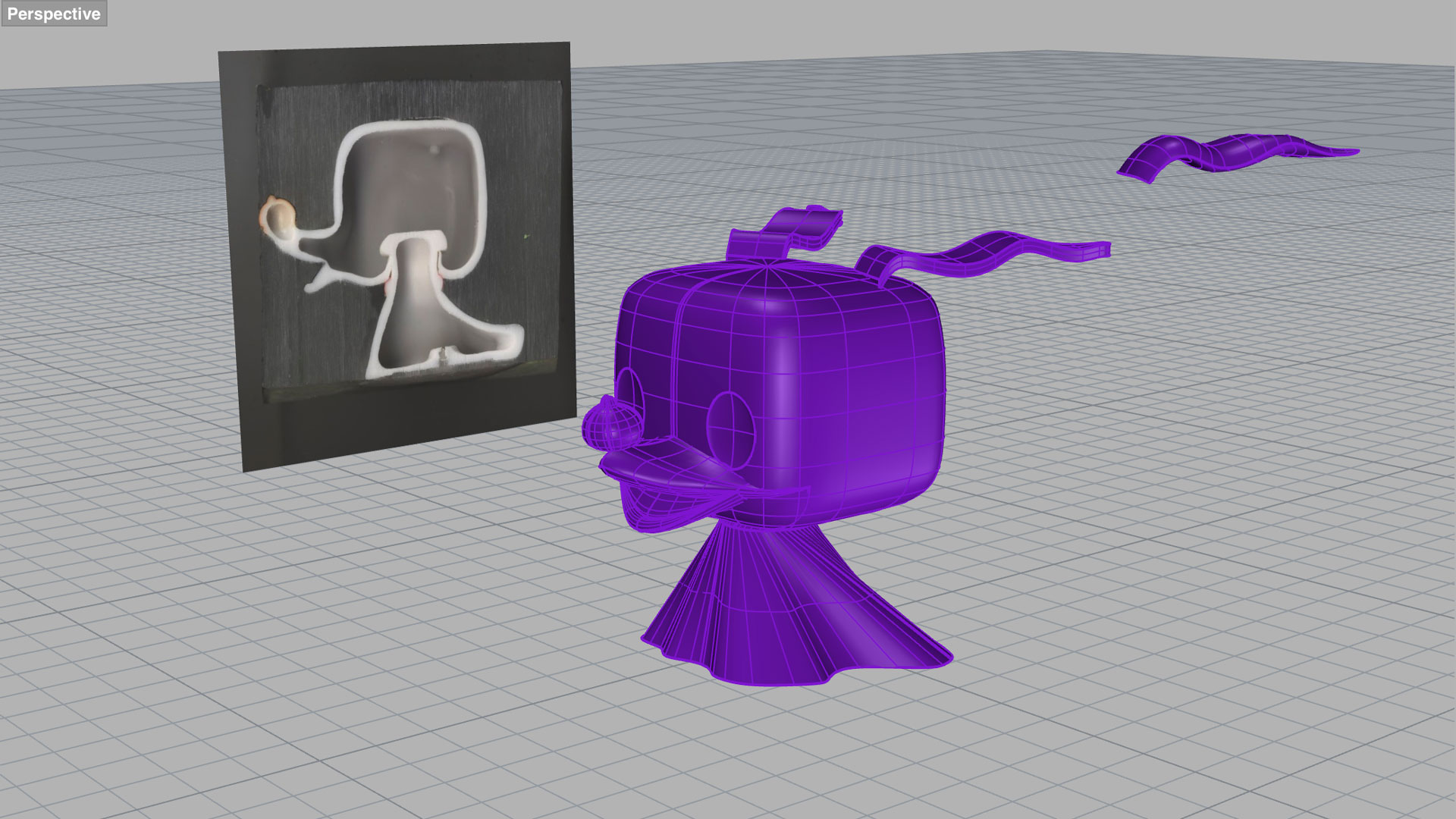
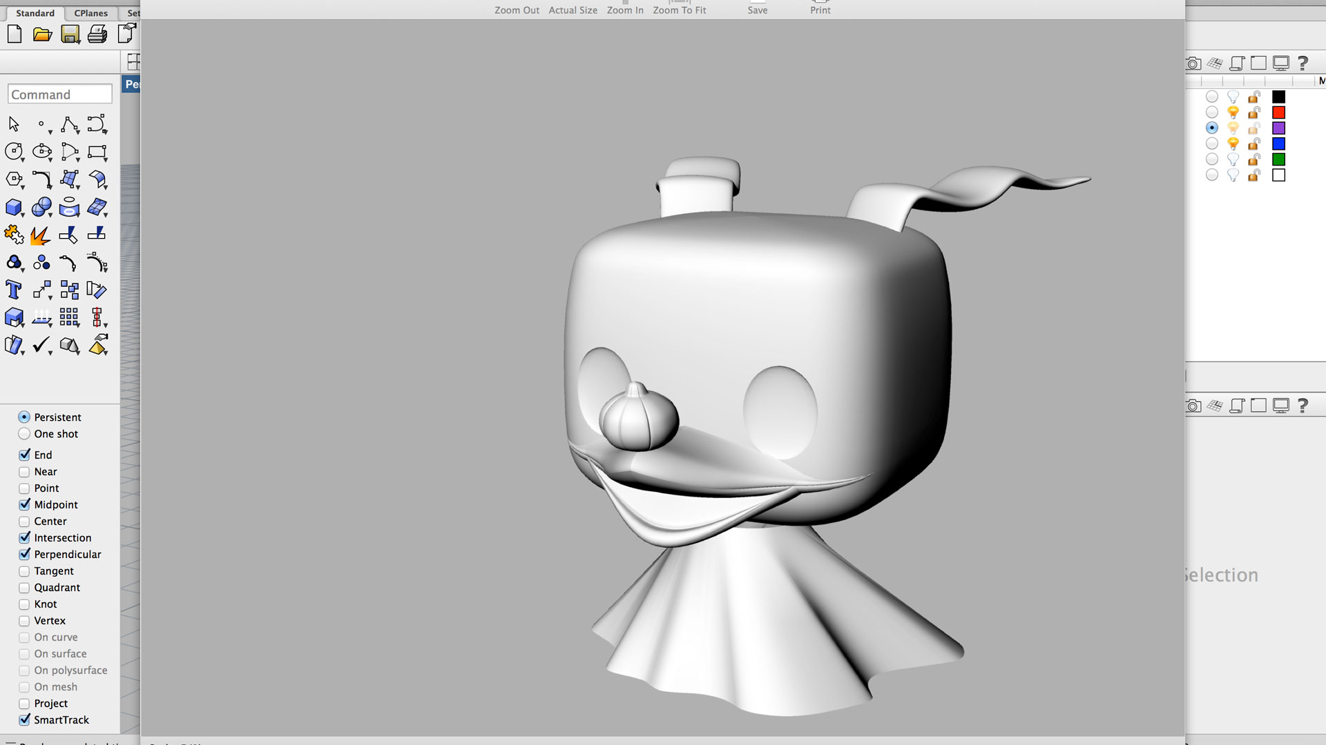
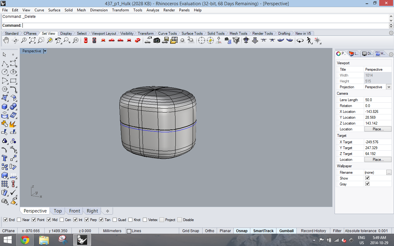
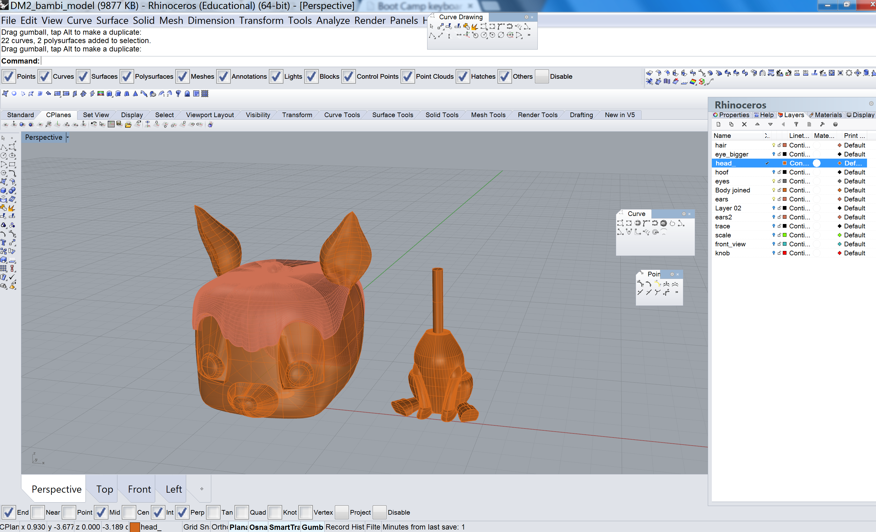
This past week, Jasmine and I finished off the last few parts of our Rhino model. Using a combination of curve networks, loft, sweep, revolve, rail revolve, edge srf, cap, and boolean commands, we managed to complete Bambi’s eyes, hair, ears, tail,  arms, and legs.

DM_p2_Oct29_1

DM_p2_Oct29_hair_offset_loft

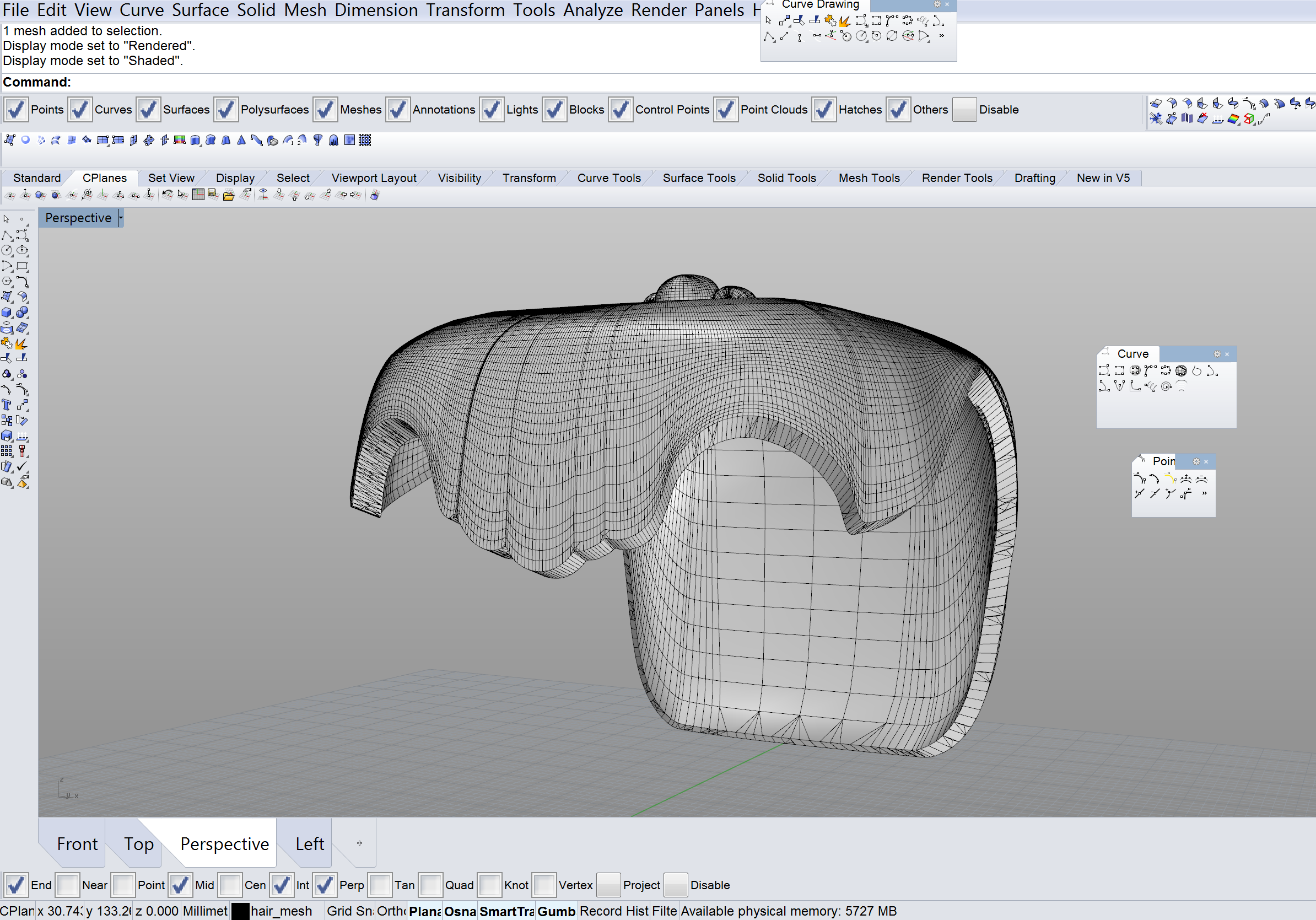
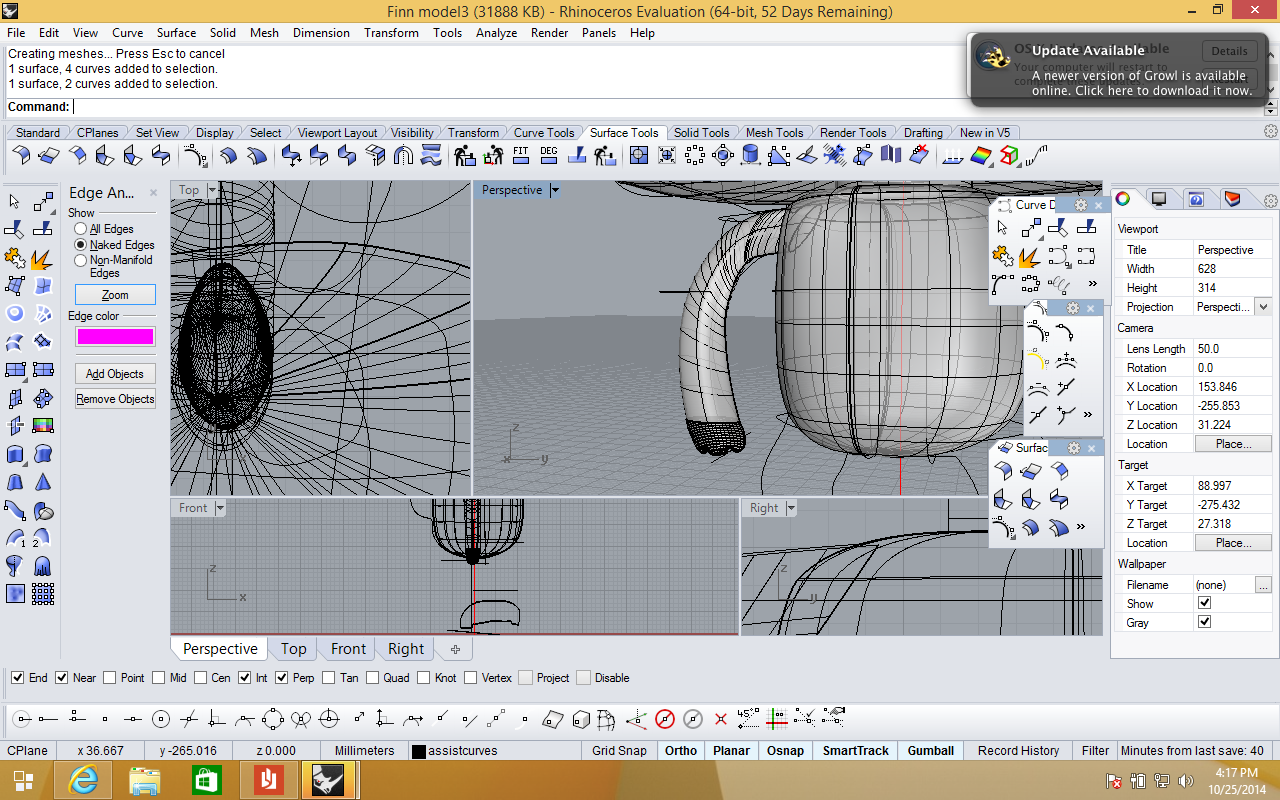
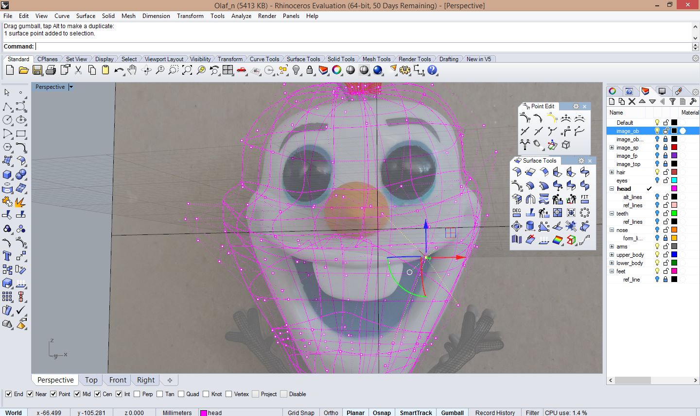
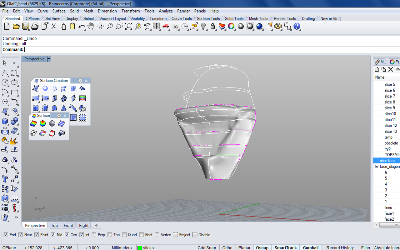
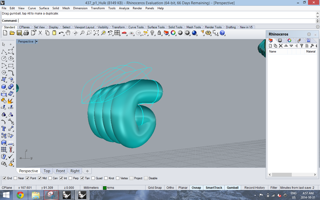
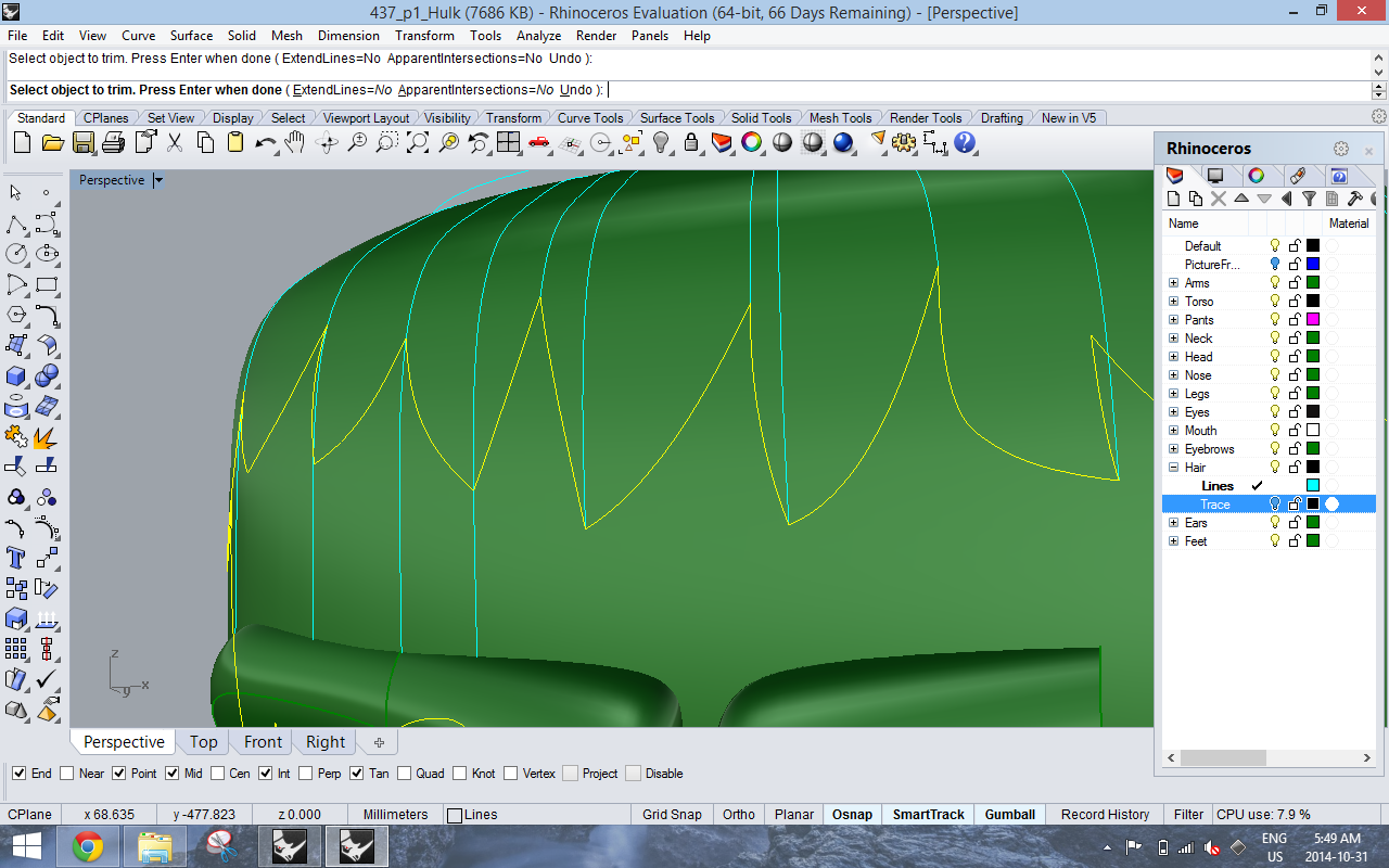
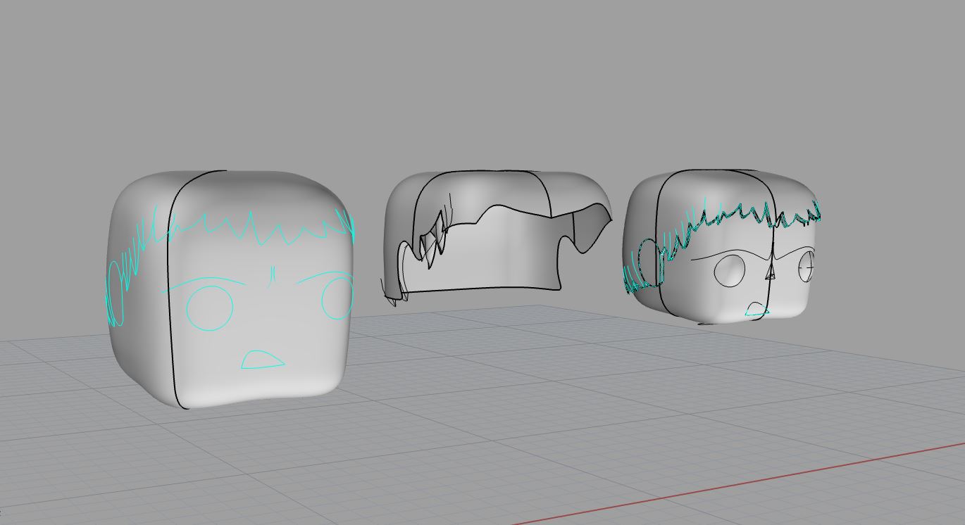
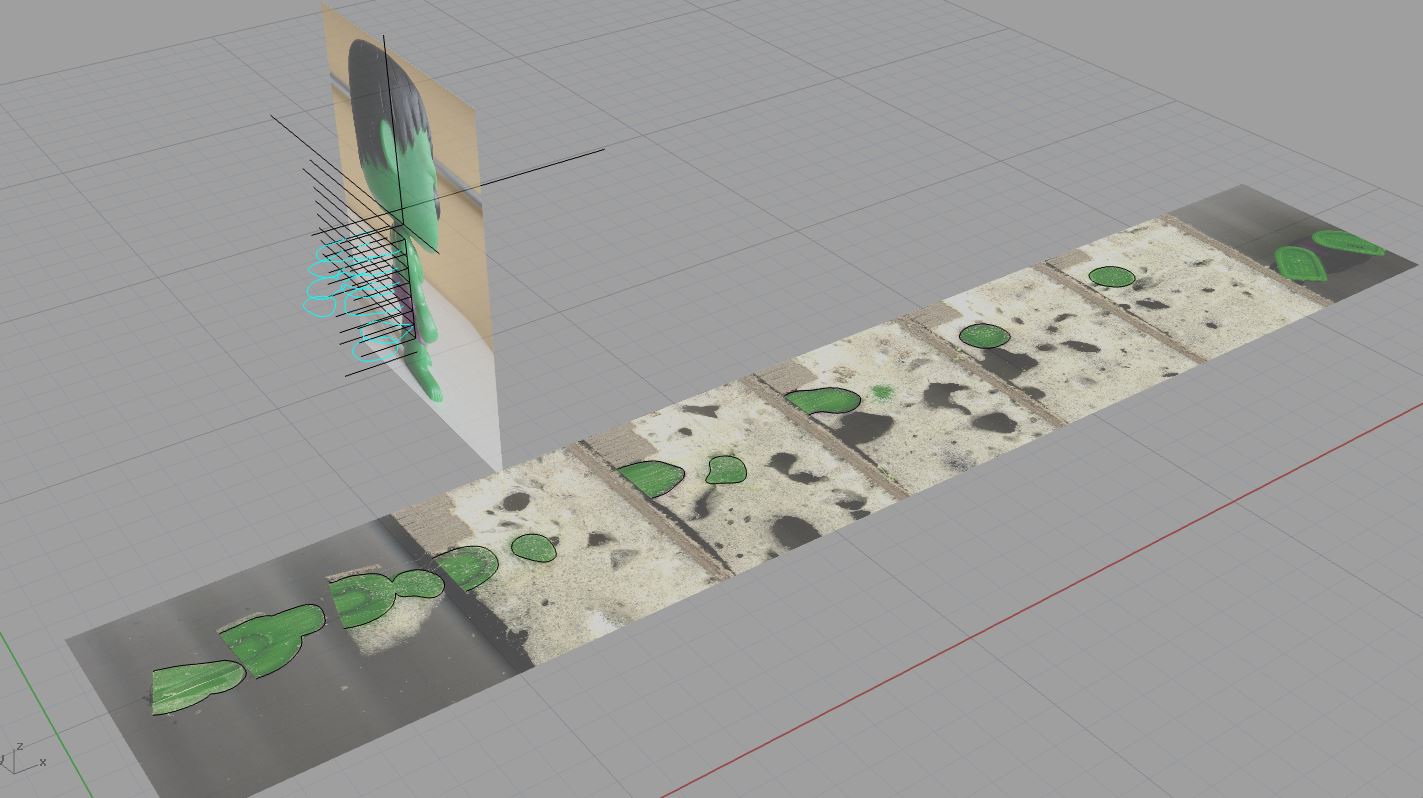
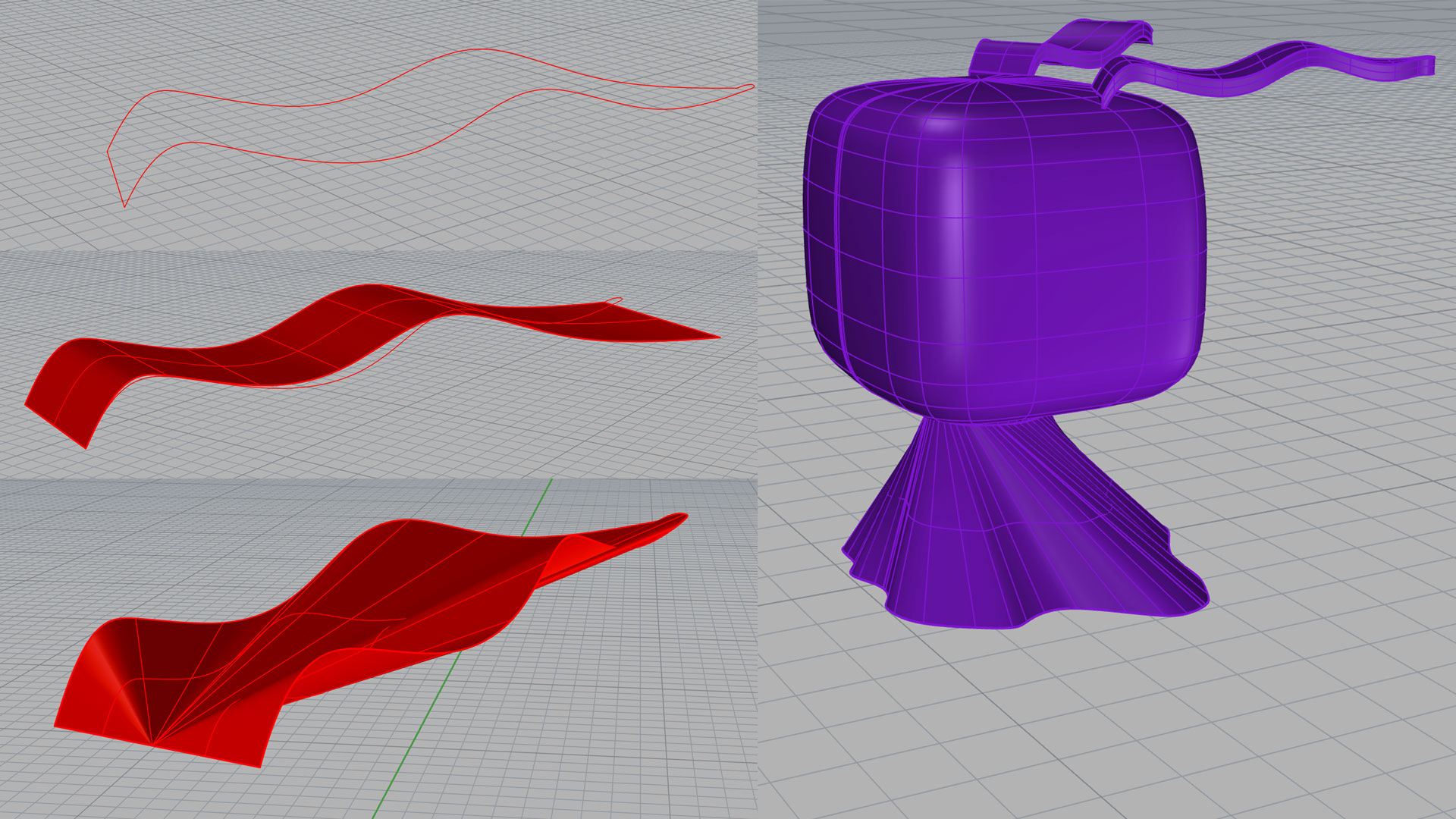
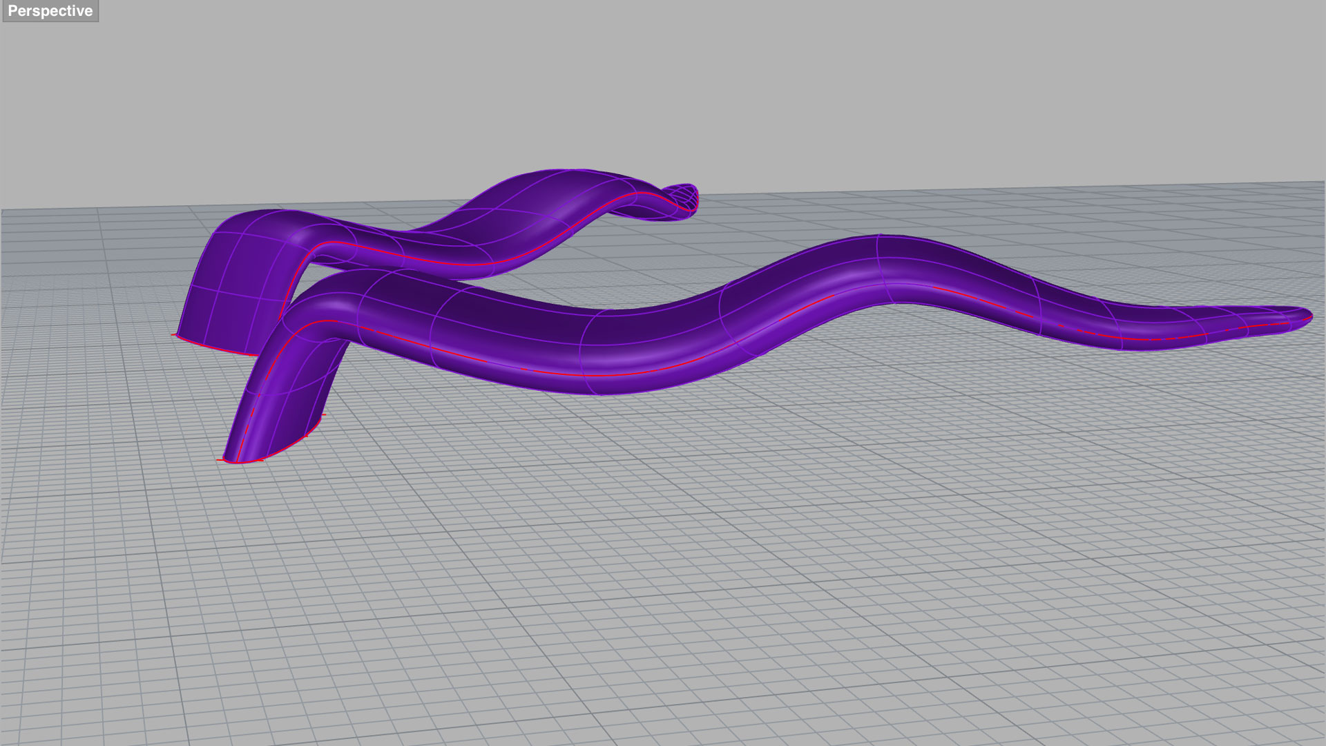
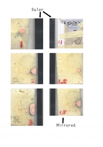
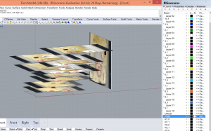
For the hair, we extracted iso curves from the main massing of the head and traced the general shape using photos of the front, side, and back views.  We then used curve networks, and then extracted iso curves again. We then adjusted the new iso curves until we were fairly satisfied with the shape and used the curve network command again. Jasmine and I found out that different combinations of the iso curves yielded slightly different shapes, some smoother than others. This process took many tries until we each achieved a shape that resembled the smooth surfaces of Bambi’s hair. After that, we offset the hair and lofted between the two surfaces.

DM_p2_Oct29_left_view_rod_offset


DM_p2_Oct29_rod_boolean

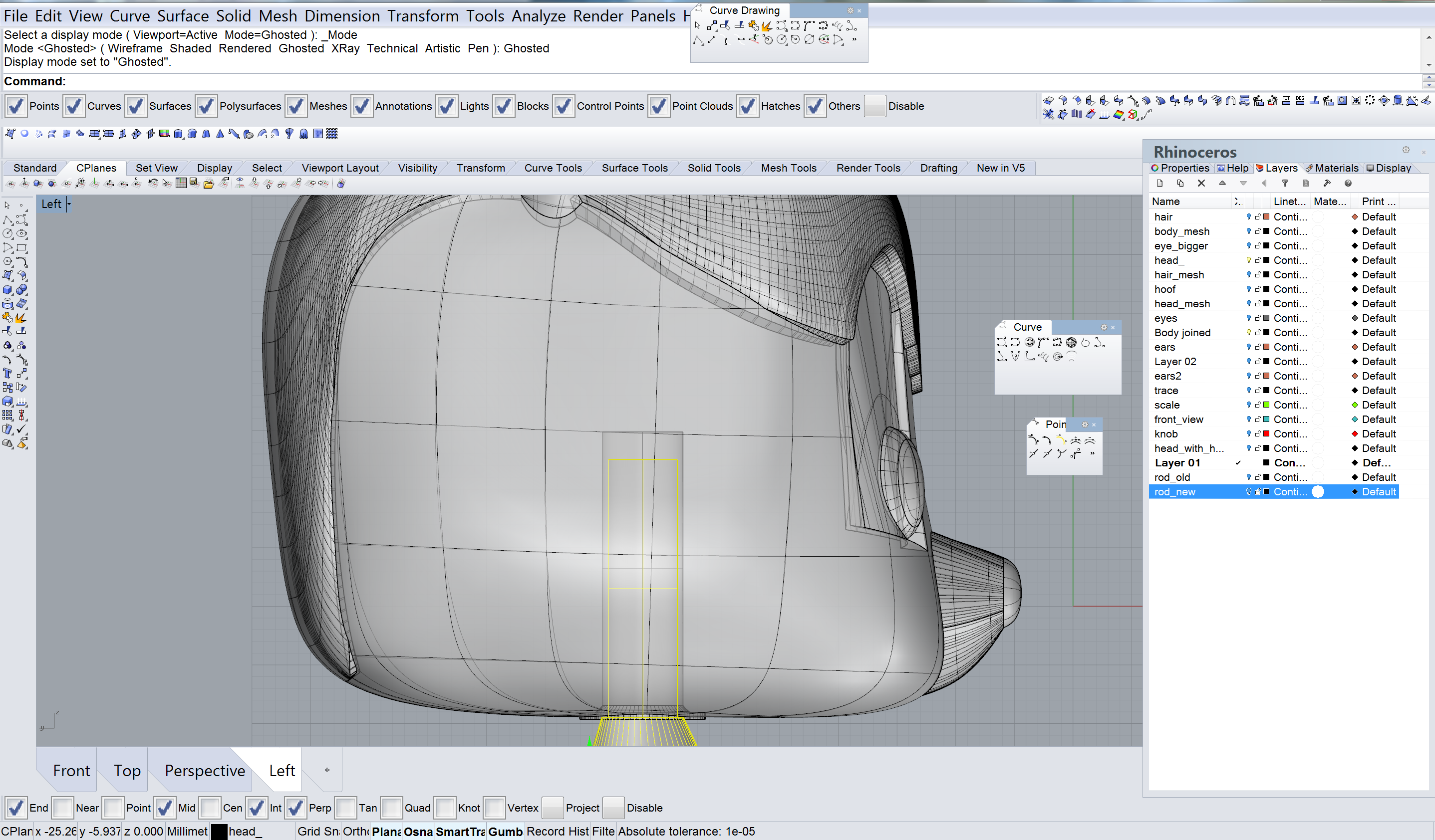
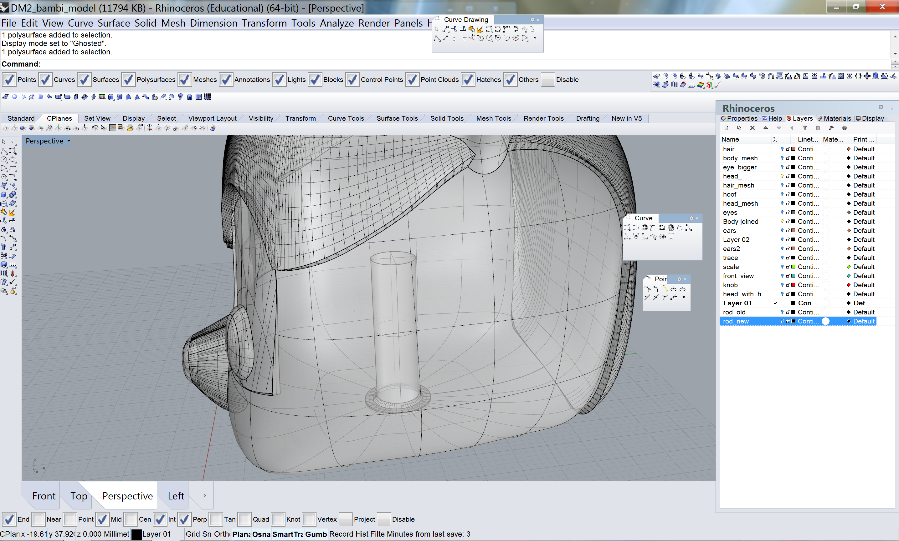
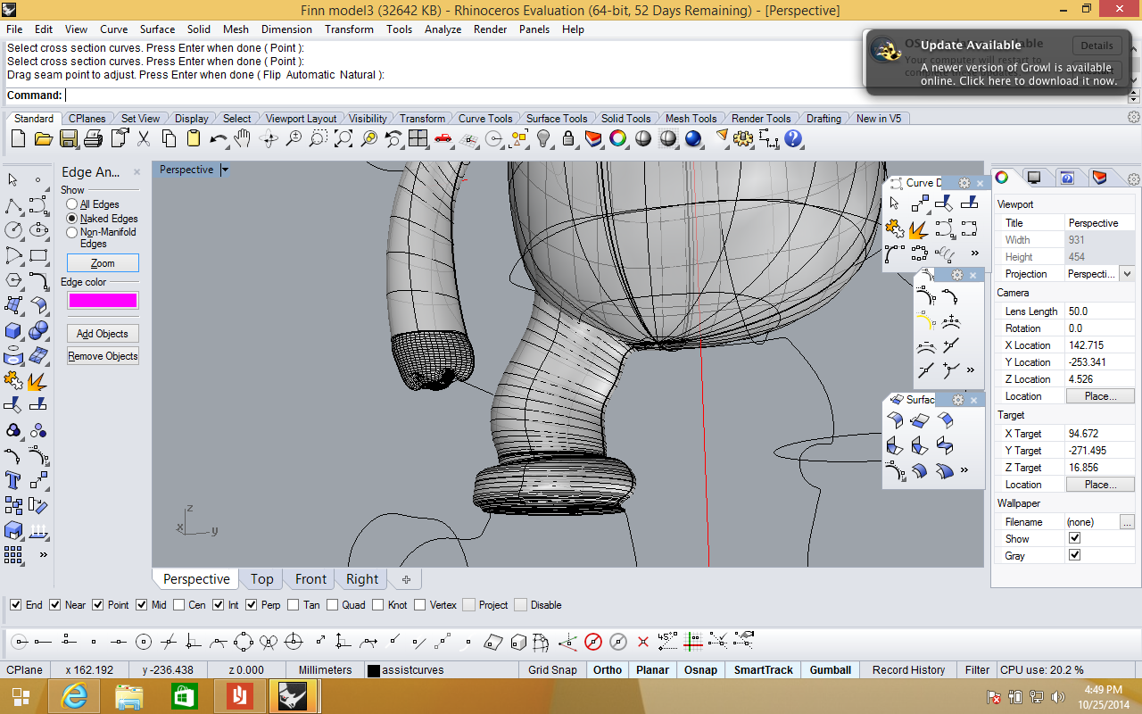
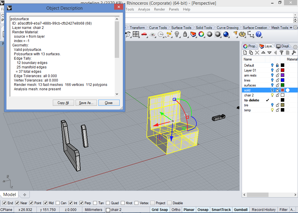
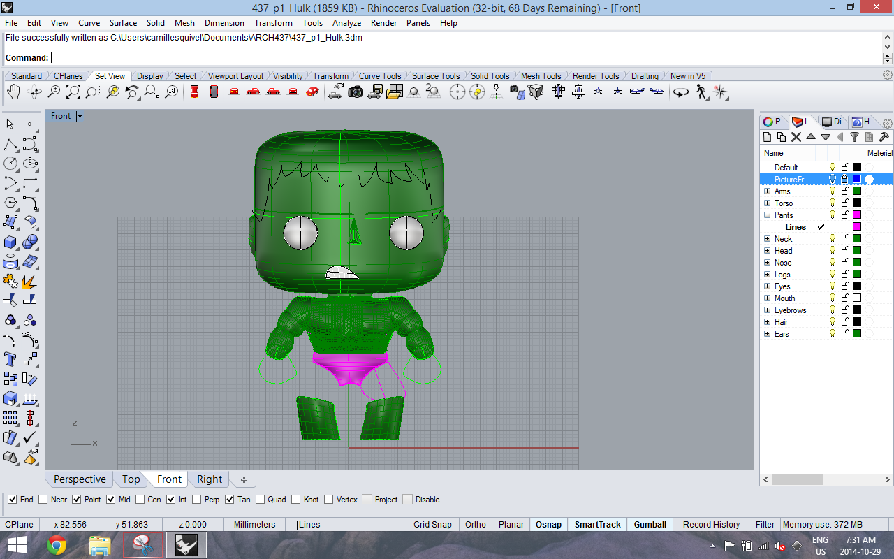
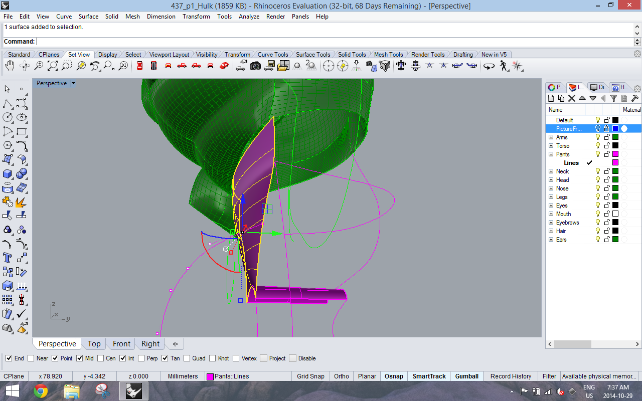
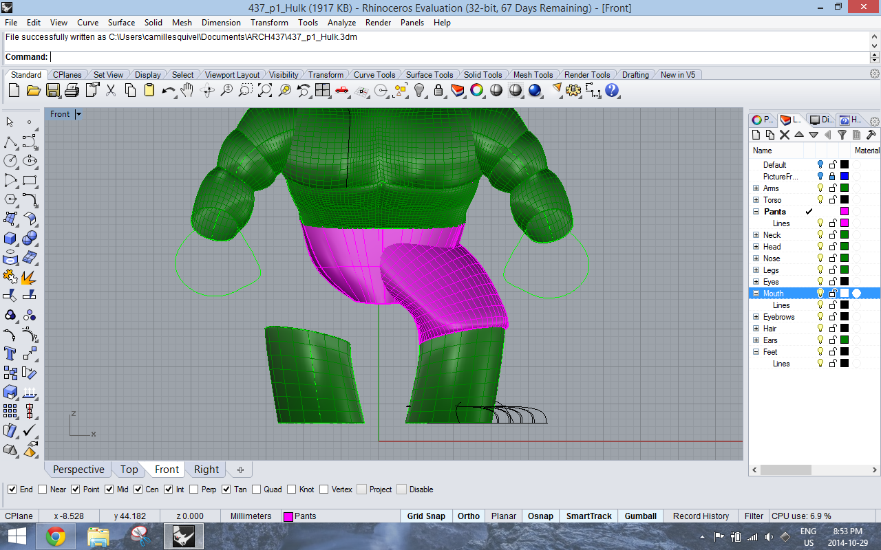
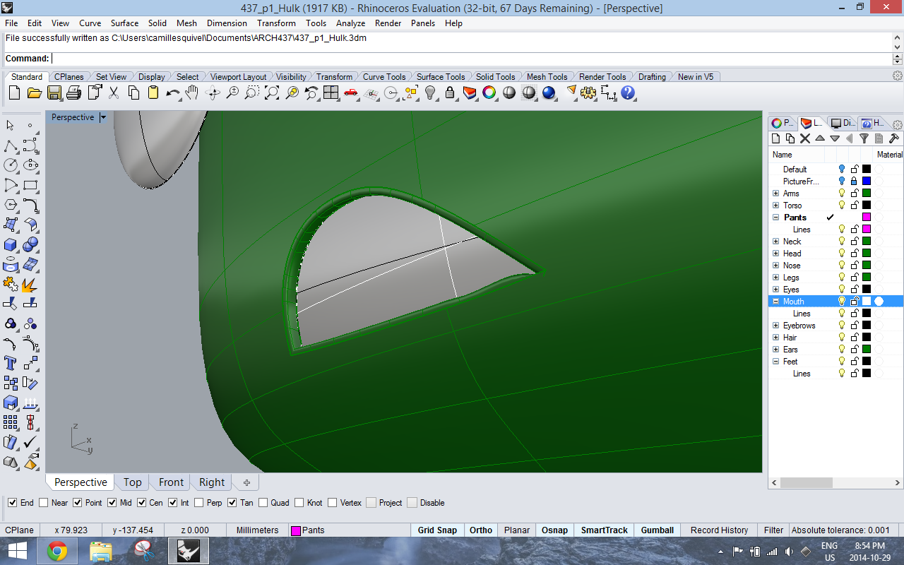
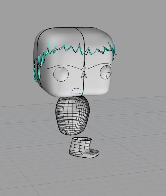
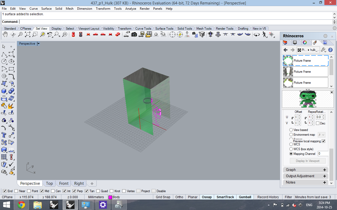
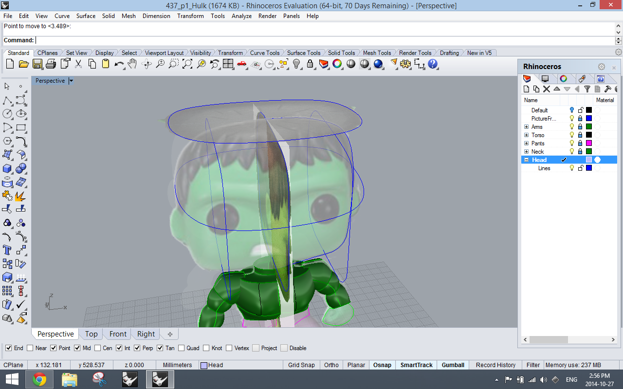
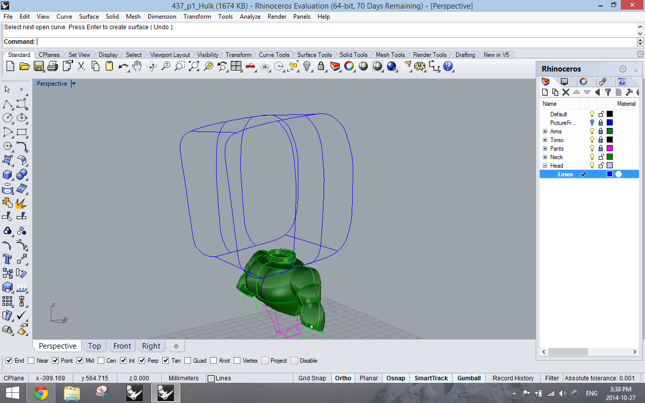
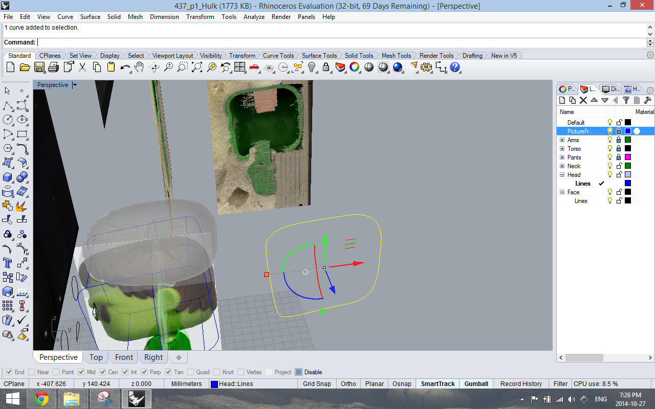
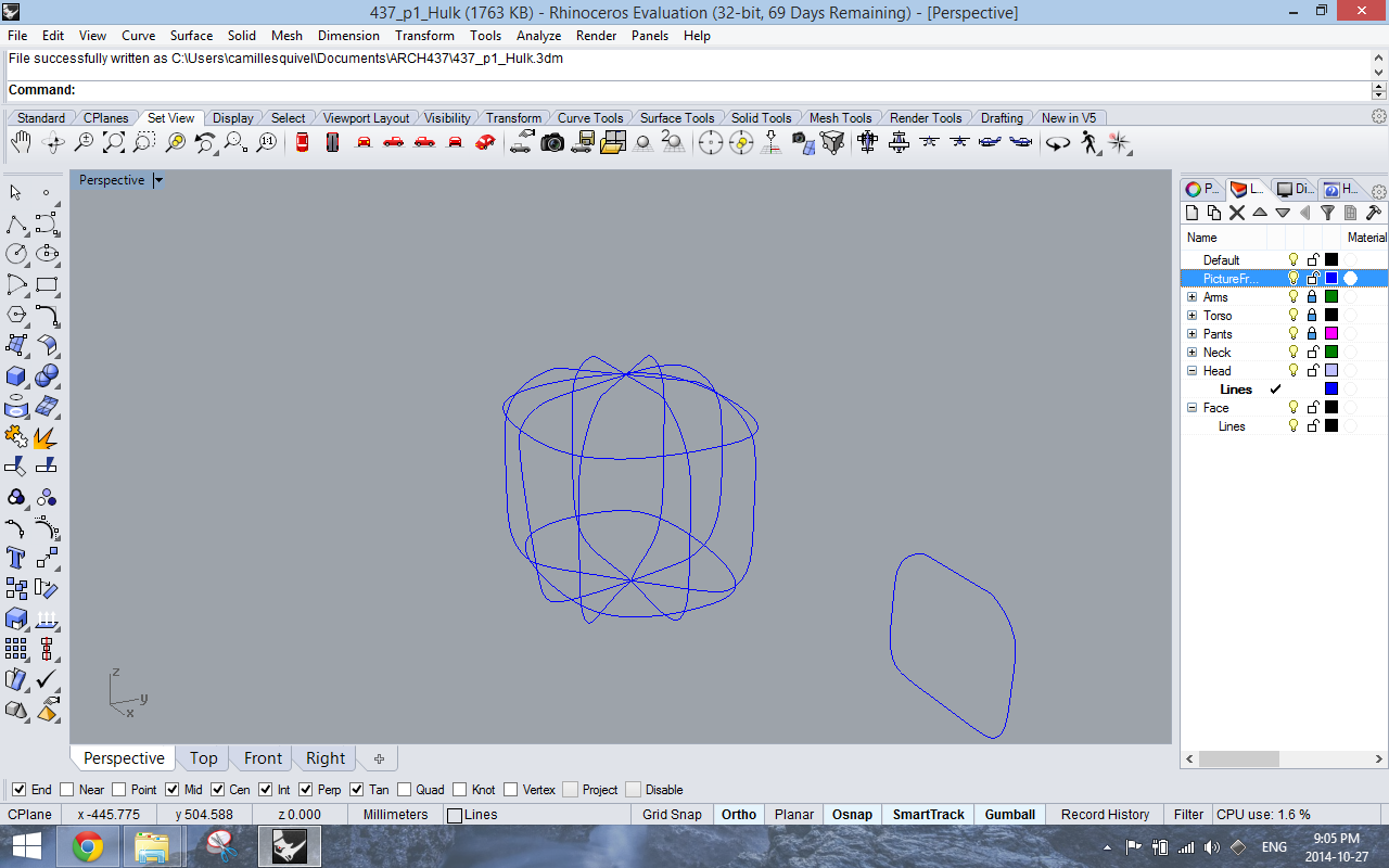
In our last blog post, Jasmine mentioned that we were trying to make the heads of our models turn. We decided to simplify the original “knob”-like turning mechanism in the toy to a basic cylinder. Using an offset of 0.5 mm, we created a cylindrical void inside the head which would allow the neck to turn. After discussing with some classmates, Jasmine and I were careful to leave more empty space above the rod in case we wouldn’t be able to remove all the support material after 3D printing.

Bambi in Pattern Layers - Ears detail

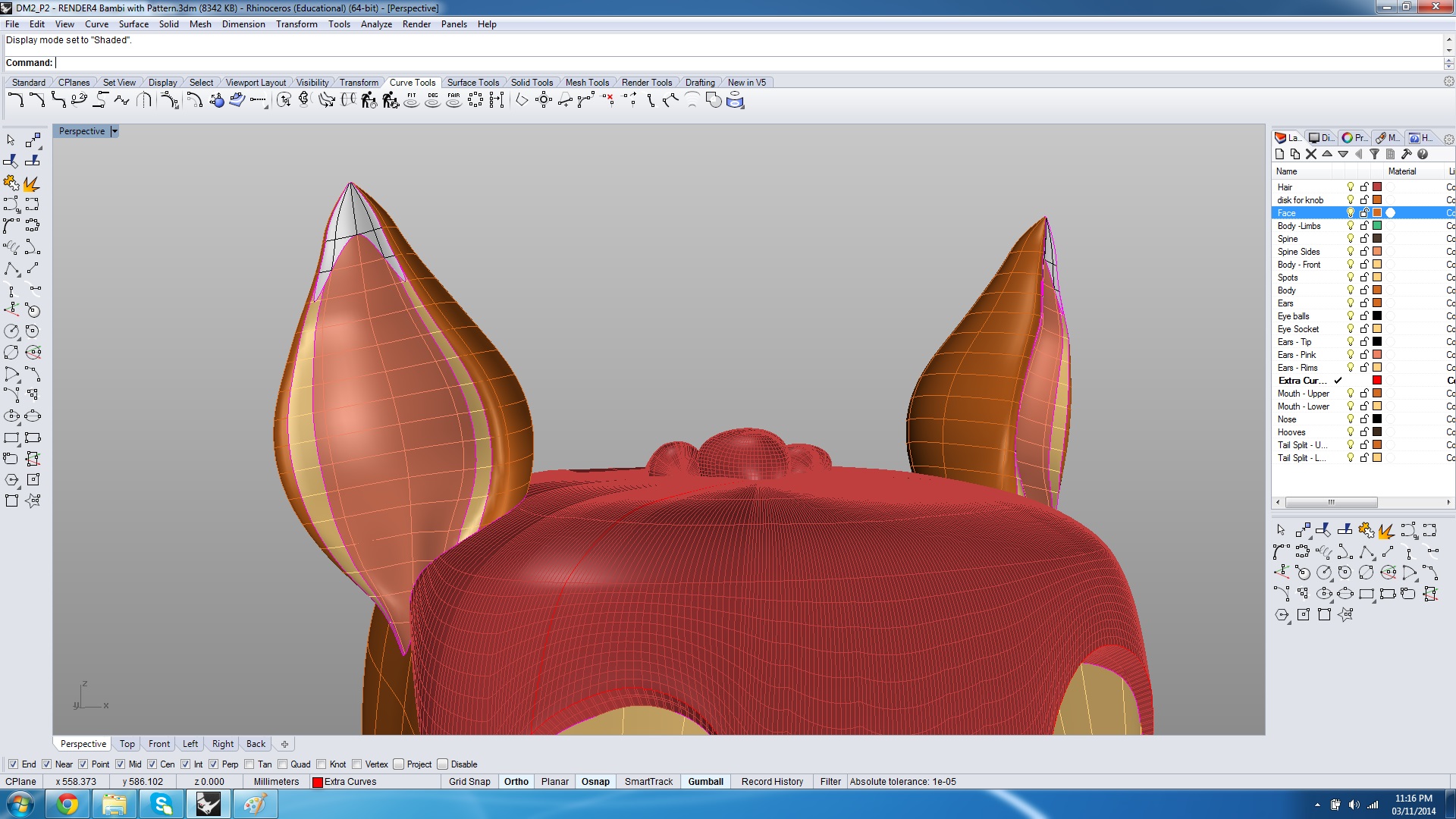
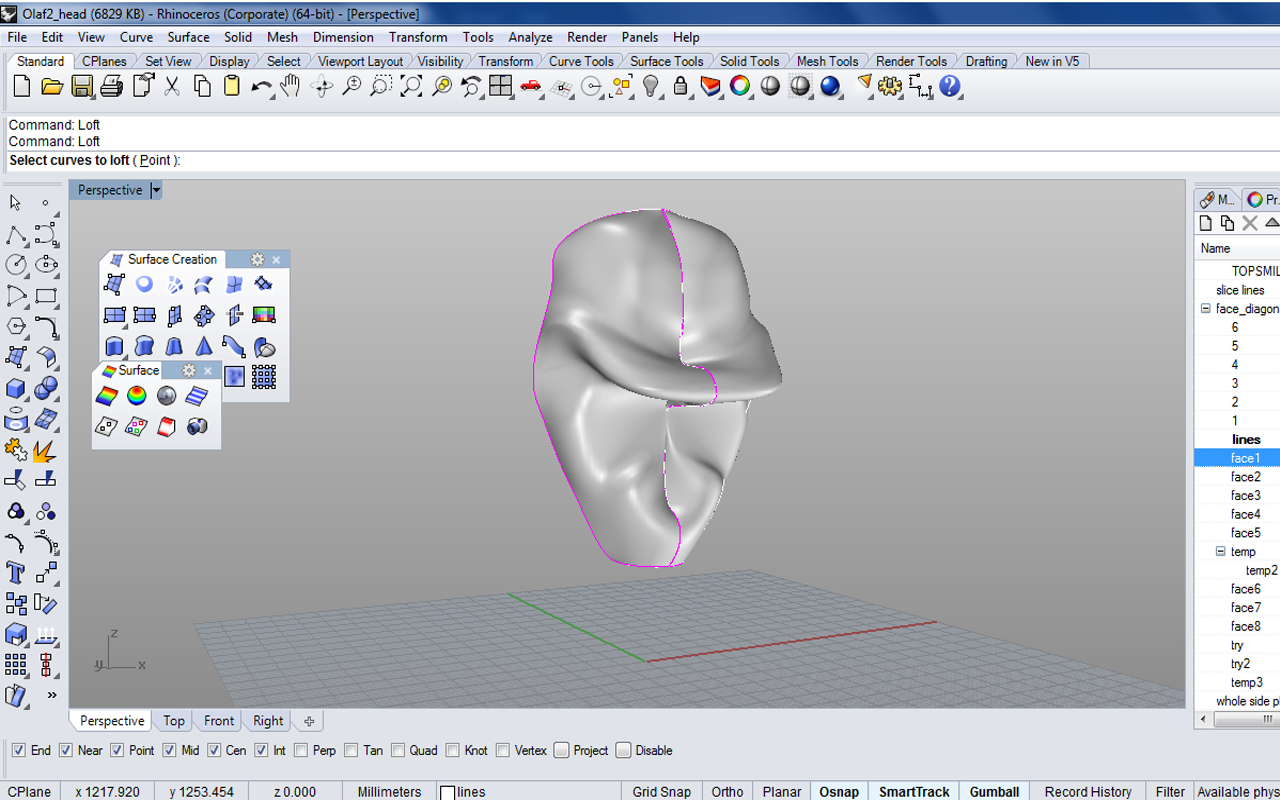
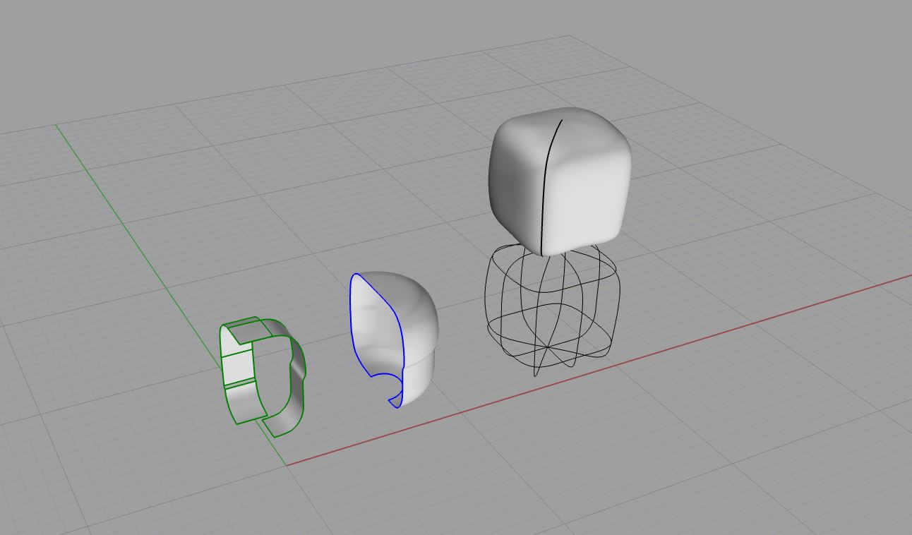
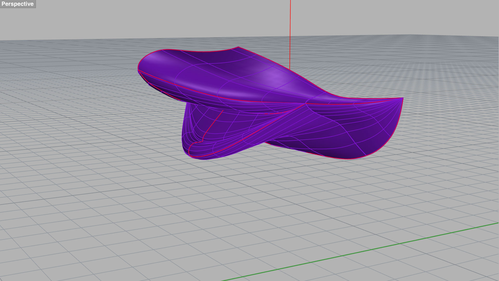
For the ears, we traced one section to get the profile curve, rail revolved, and lofted. Similar to the process for creating the hair, we extracted iso curves from this new shape, manually adjusted them, and then lofted again to generate a more precise form of the ear.

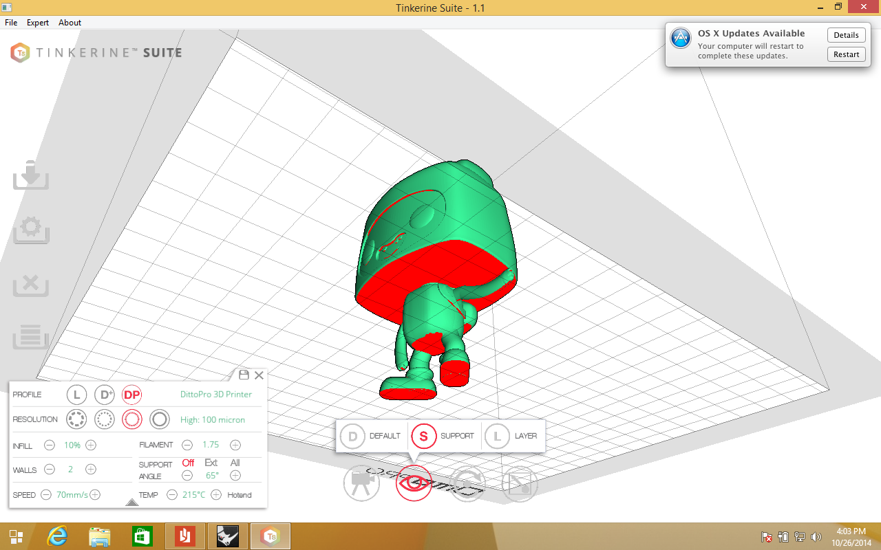
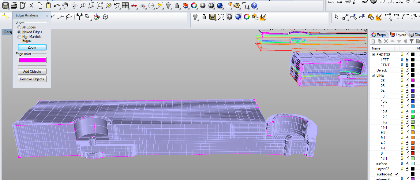
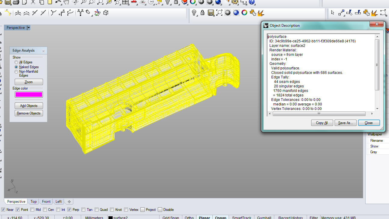
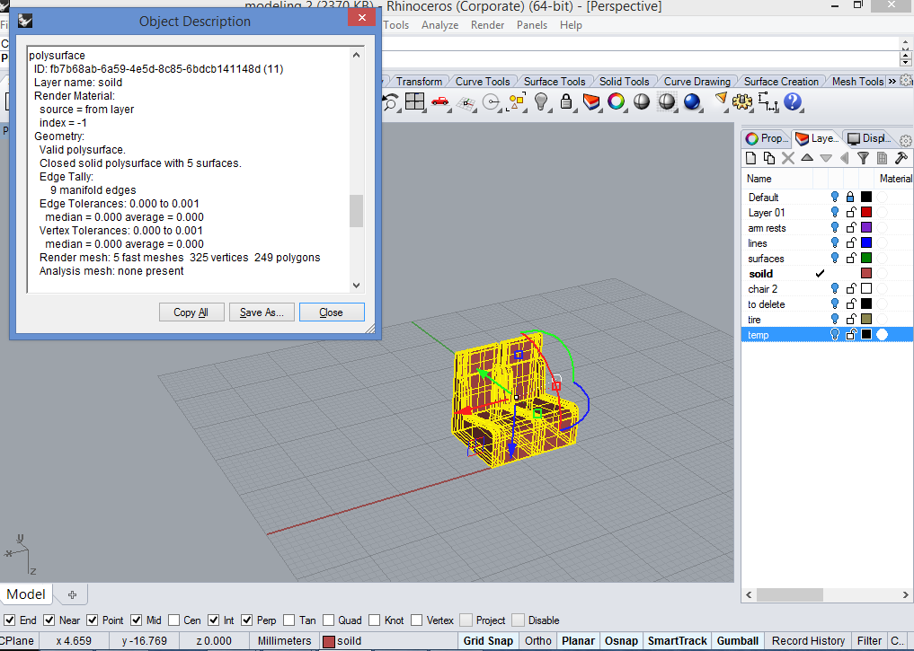
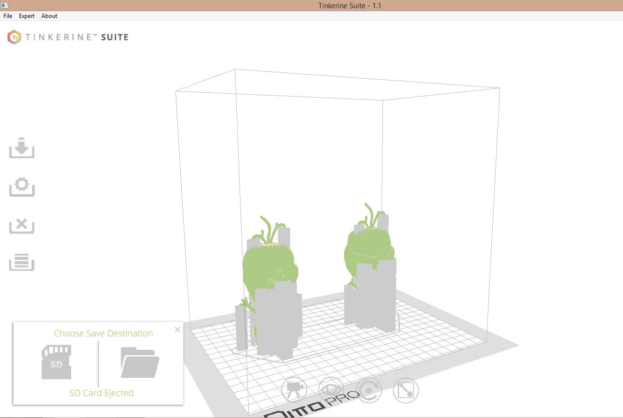
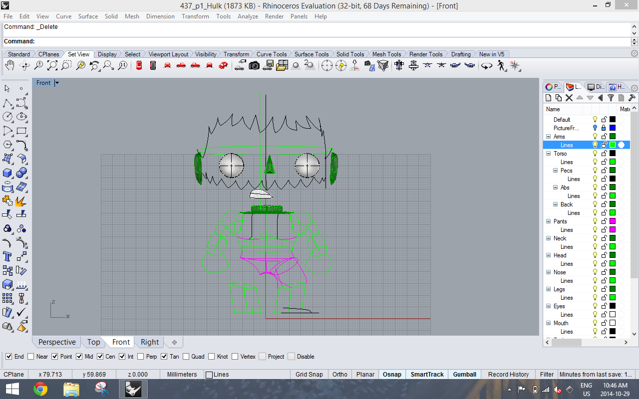
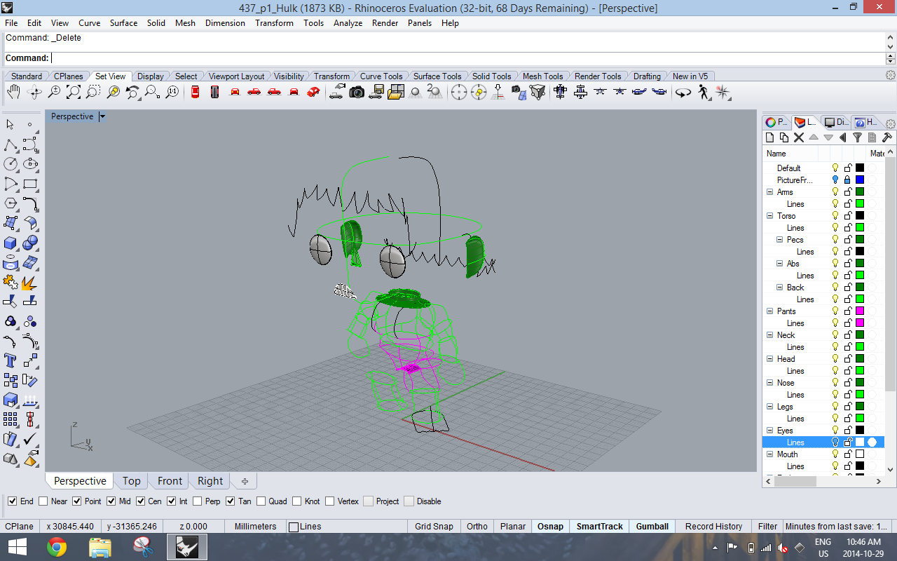
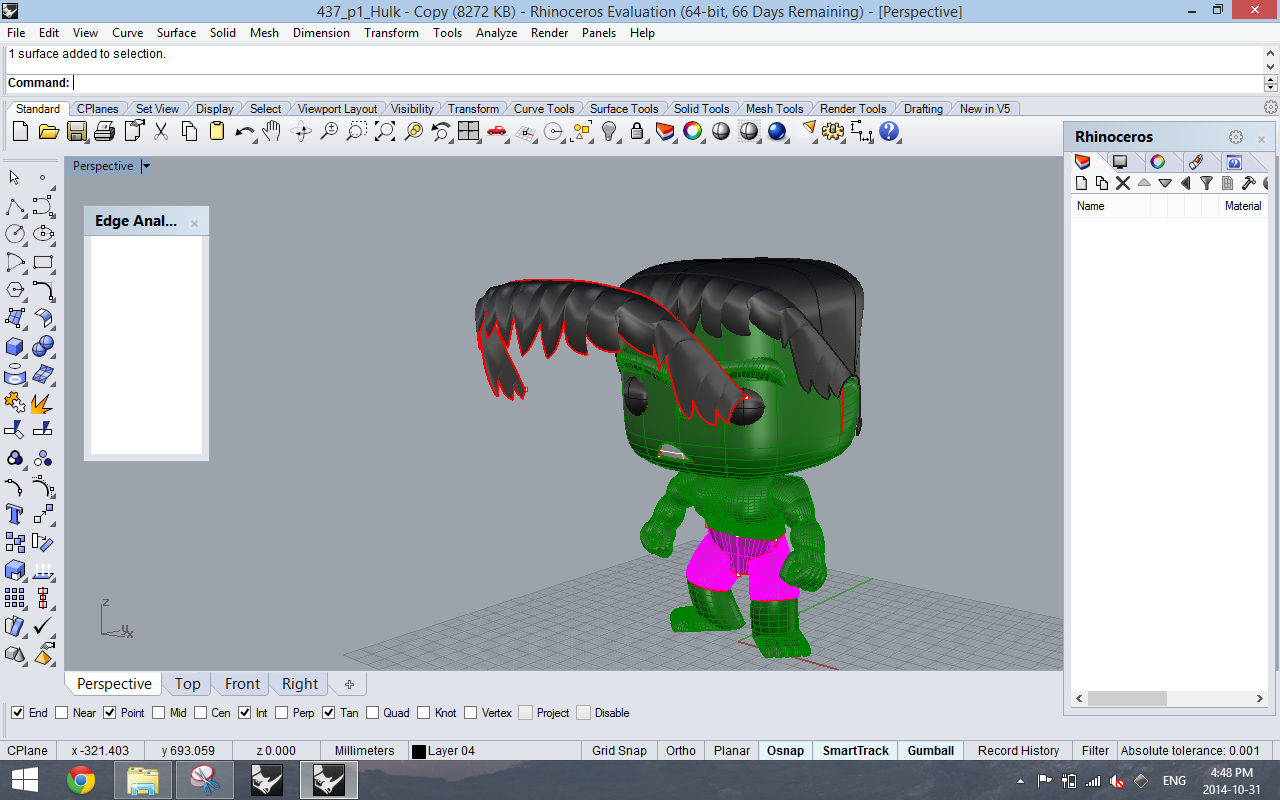
After making sure that our model was properly joined/booleaned and  free of nasty naked edges, we were ready to prepare our file for 3D printing.

Our first printing job took about 2 minutes… Due to scaling problems, we ended up printing our model 10 times too small. We soon realized that Tinkerine had taken our model (drawn in centimetres) and changed the units to millimetres. We made the adjustments and proceeded to print again.

We had hoped to print our model in white, but due to temperature issues, and the spool tangling within itself (which happens when the spool is too large to fit on the back of the printer), our second print was a failure to say the least.

2014-10-30 22.51.48

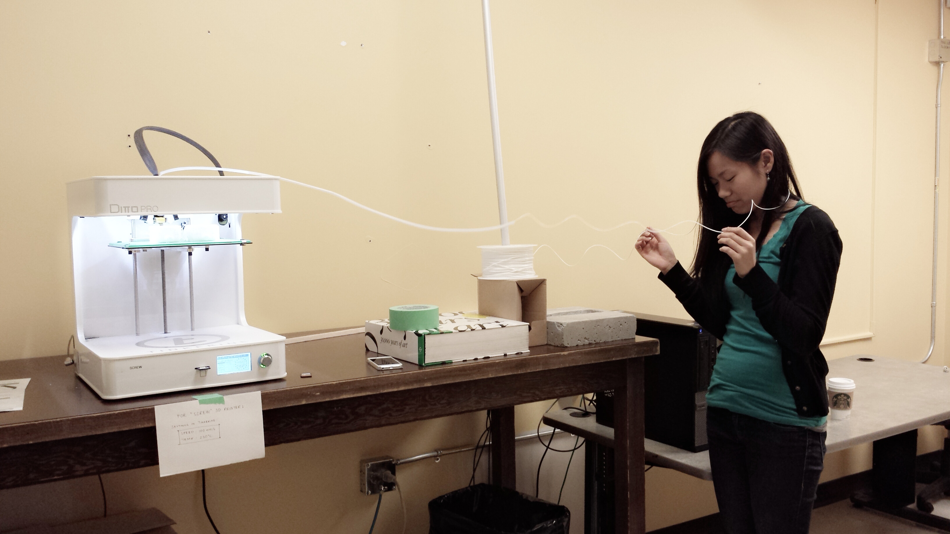
For 10 hours, we watched our print job while manually untangling the filament as best as we could.

2014-10-30 23.57.25


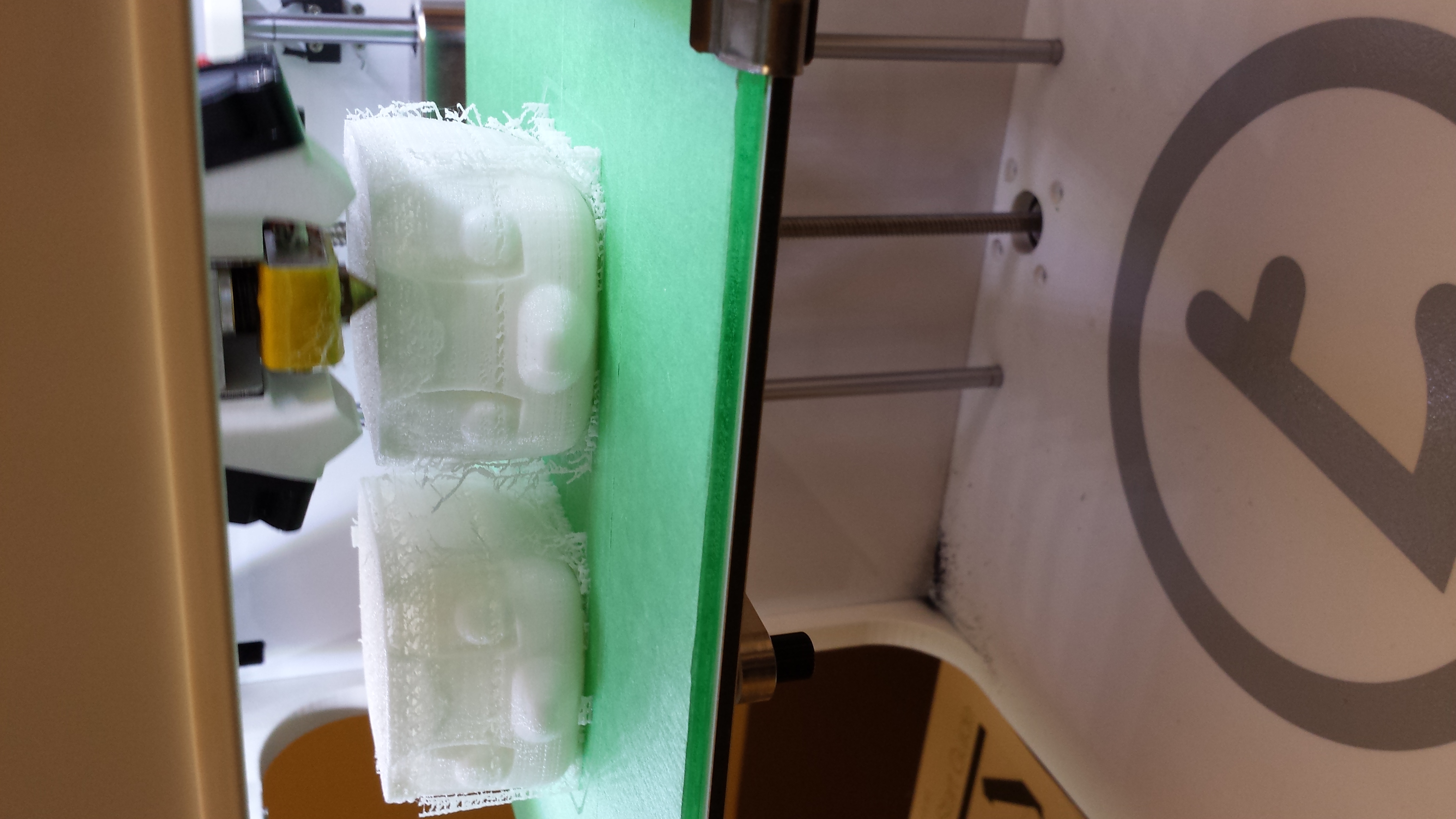
An open window and other temperature issues caused breaks and gaping holes in our model.  Another lesson we learned was not to leave a print job unattended. After a frustrating 10 hours, we went home for the last 5 hours of our print jobs for some much needed sleep. Unfortunately, when we arrived at school the next morning,  just when we thought things couldn’t get any worse, we discovered the following scene.

10746651_10152370396771135_1521672084_o

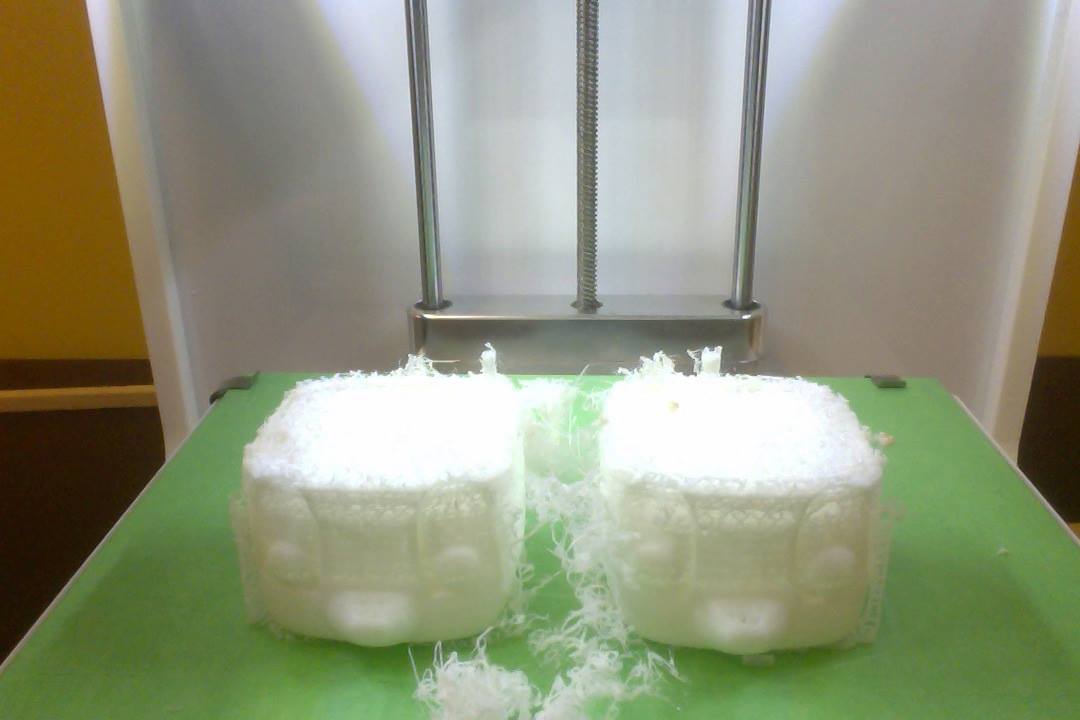
Without anybody to untangle and help move the spool along, the filament seemed to have stopped feeding into the machine, leaving our model incomplete.

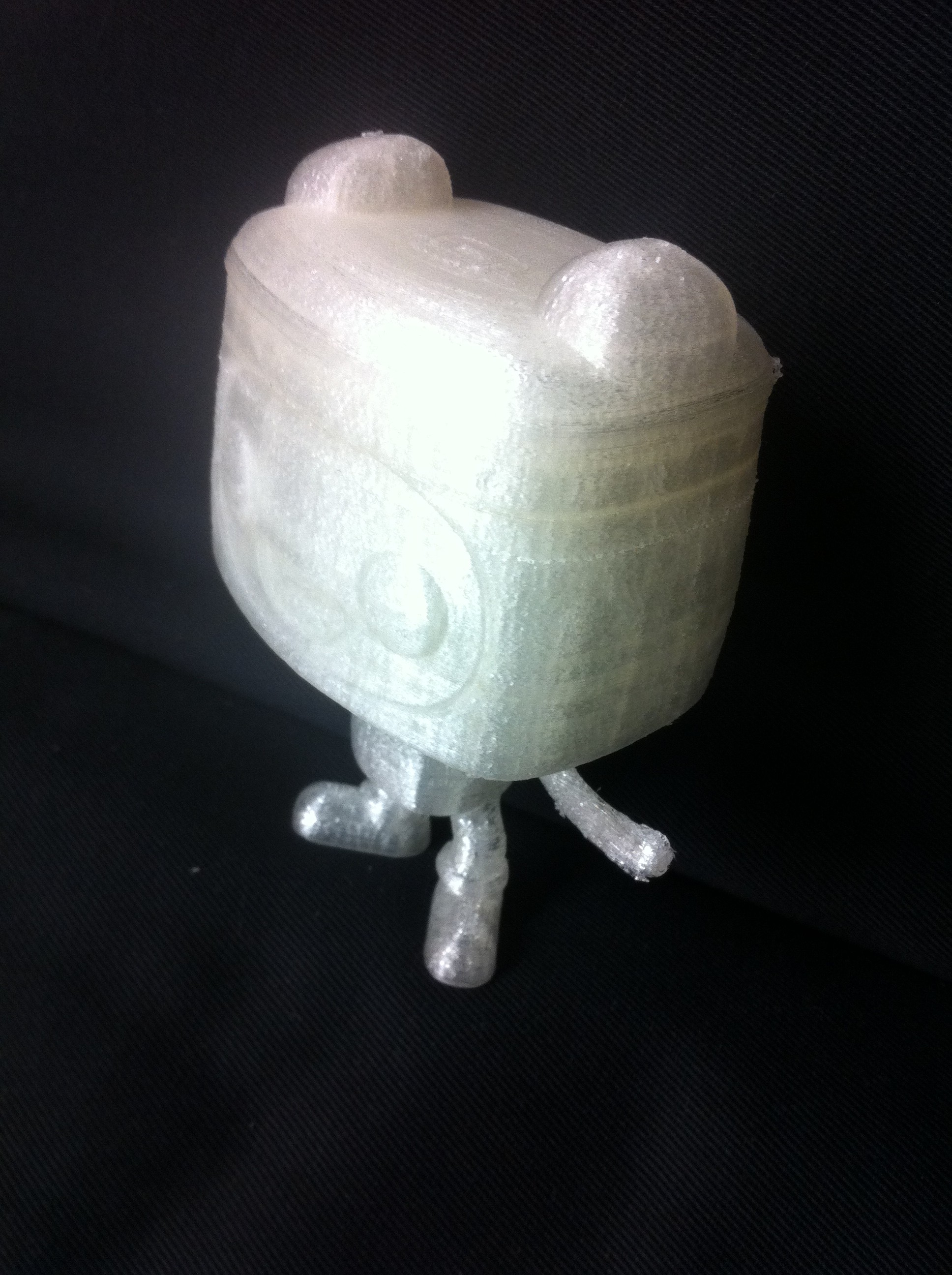
Our third attempt was much more successful. This time, we decided to split our files onto two separate printers and opted for the clear filament. This time, there were no temperature issues and the print job went smoothly and fairly quickly, taking just under 3 hours. 2014-10-31 18.03.31

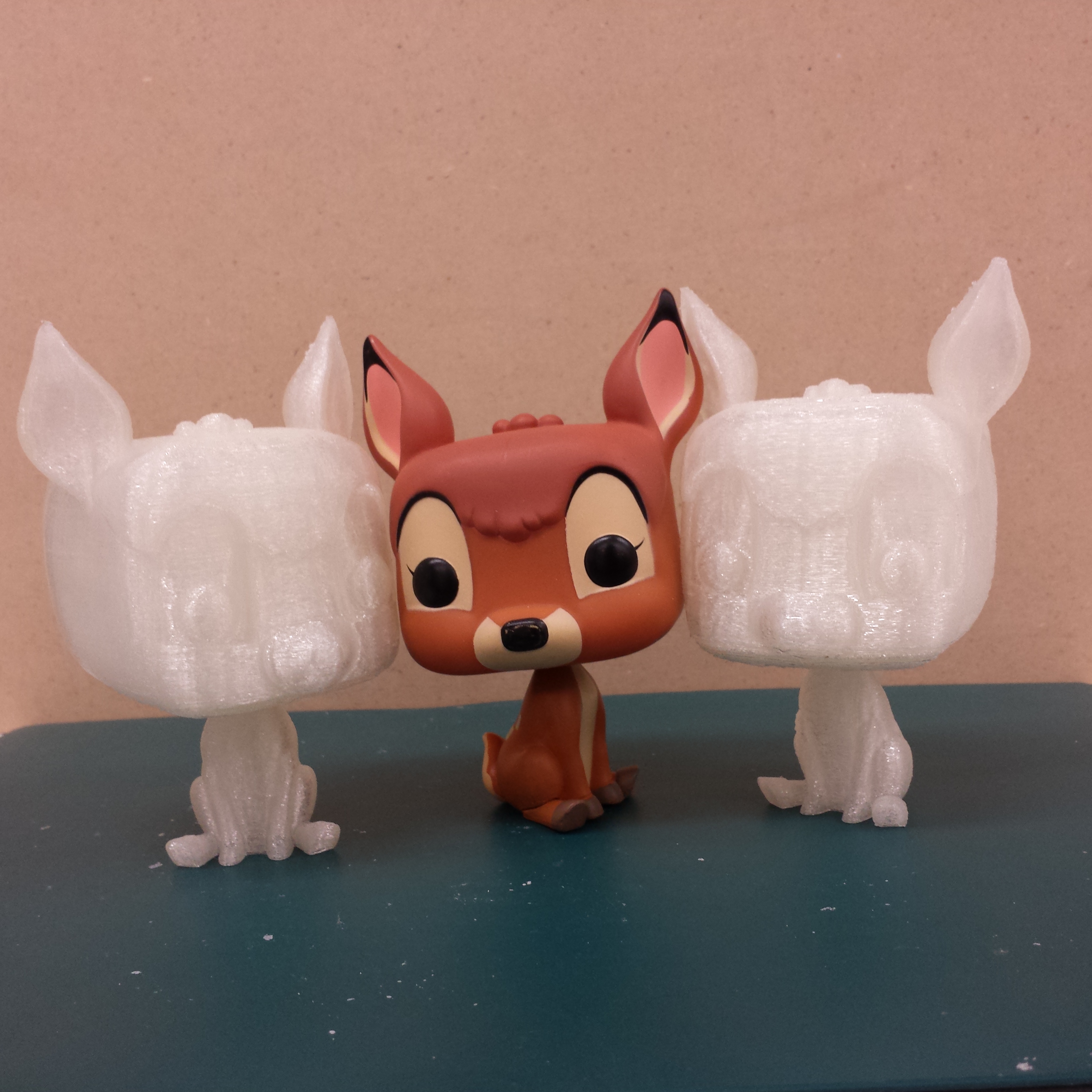
Overall, Jasmine and I are happy with the results. The neck connection worked out well, and the heads were able to turn! It was indeed a happy ending to what seemed like a dreadful beginning.

Finishing Finn


Hands


This week I put the finishing touches on my rhino model. My greatest challenge was learning some of the ways in which I can sweep over a surface and maintain a solid polysurface, as I did a lot of sweeping for the arms and legs. For the arms, I used sweep1, sweeping into the body to insure a strong connection. I closed the shoulder side using patch and the hand side using a mesh that was sculpted into the shape of a hand. For the fingers, I turned on control points on the mesh and sculpted the fingers using the physical model as a reference for estimating form.


Legs


For the legs, I used sweep2, as the rails were sightly more coplex. I used several section lines to create the bulge of the sock before the shoe. A patch seals the connection between leg and body, and a simple edge extrusion insures a solid connection between the sock and the shoe.


Leg Rotated


While modelling the shoe I learned that it is much easier to create objects with vertices orientated along the X and Y axis, then rotate after the modelling is complete. This way, I was able to perform all of the snap commands necessary to form my shoe. I used rail revolve, extrude line, join and boolean union to make the leg into a solid polysurface. I also used sweep to create the backpack straps around the arms, and rail revolve and reflect to form the backpack.


Tinkerline


Finally my model was a closed, complete polysurface ready to export to the 3d printer. In tinkering, I experimented with infill and resolution settings until I finally got a perfect print. I ended up printing the head separate from the body, and attaching after the fact. This reduced both time and structure material required.

Screen Shot 2014-10-29 at 11.49.43 AM

In a new Rhino file, I exploded my model and re-organized the layers based on the colour of my model. In keyshot, I exported the file and got a nice, solid render with accurate colouring.

3D Print


Magic School Bus

Unfortunately, instead of modeling our bus as a solid, Shizuka and I were modeling the shape using planes. We only realized that this was the wrong way of modeling once the Boolean command was not performing.

BUS-10-20

BUS-10-22

4

And so, we had to join, cap and extrude our planes to turn them into solids.

BUS-10-25

bus-10-27-WHAT

5

Once all the objects were converted into solids, it was like magic! All the functions started working flawlessly!

BUS-10-27

BUS-10-28

3

Modelling Olaf 3

This week Darcy and I worked on modelling the face which required a variety of attempts and methods to accomplish. Using a curve network and then editing control points to shape the smile and correct the volume was one method. In order to get both sides of the face to be symmetrical, One half of the face was modified and then mirrored.

olaf_controlpts


olaf_fullbody


The other method was using horizontal slices at different heights  and then lofting them together to produce the face volume. This made the bottom part of the face look good, but distorted the top half. Then we tried using vertical slices cut along diagonals of the face and creating a curve network from those. This produced a good top half of the face but distorted the bottom half. Next we tried putting those two together but couldn’t get them to connect properly.

week3_3

week3_2

week3

week3_4

Once the face was completed, we created the eyes using distorted spheres, and the teeth with a curve network. After that we boolean union all the parts together to get ready for printing. We ran into some difficulties when trying to mesh the object which required repairing some shapes to eliminate naked edges and make it a closed solid and Andy helped us with manifold edges and how to fix them. Now we are ready for printing.

olaf_both_tinkerine

Hulk: Finishing the Body + Adding Details

Finishing up the body – continuing to use my strategy of breaking up surfaces and segments then joining things together later as Hulk is not symmetrical at all points.16 17 18 19 20

Lots of things continue to need refinement…21

Successfully using Blend Surface after Tam’s recommendation!22 23

I definitely put off the fists as my last task as it was a hard one to conquer. Edward suggested sharing pieces among group members so the blue was created by Christina (below). Given the style of Hulk however, I thought it didn’t quite match which is the difficult part with having different techniques in Rhino I learned.

24

After an enlightening power-shower, I realized that given the scope of the project and seeing the 3D models already printed by peers… I realized many details are lost in print. I used this to my advantage and any harsh curves created from using the Pipe + round curve tool would actually work for me.25

Last to take on – the hair. This was definitely the most frustrating part of the whole project because I was so close to finishing but the technique that my group members/partner used… just wasn’t working for me. They projected the curves traced of his hair in front and right view onto their heads, split, offset then finally capped it.

Mine was not splitting unfortunately so I had to seek other strategies…

26 27

Finally getting close to something… this was the best I could get (although I wasn’t happy with the result). Unfortunately, after my first print – the hair caused a lot of issues.28

Curved surface experiments

I began the construction of the head by experimenting with a variety of different methods to create curved surface from our section cuts. As seen below, I tried lofting, revolving and network surface. Although it is tricky to build the curves so you get any surface at all let alone an accurate representation, I had the best results from network surface. I continued to build my model from that technique.

From my sections and elevations, I traced the image and projected the curves onto the surface of the head. Then I experimented with different ways to model the hair on his head. First I modeled every strand of hair using my new found tool, network surface. It created an appealing result because it really got the volume and shape of the hair. But I realized I was getting too detailed and was working on a scale that was too detailed to come across in the printed model. As a result, I used the projected lines to split the head into hair and face and scaled the face down to create the hair line. Then, I added the facial features using shapes.

head
lofting, revolve, curve network surface with construction lines.
head details
projected lines on head, hair attempt 1, hair attempt 2 with facial features


Continuing with more section cuts the team and I created, I was able to create the torso and the legs using Network Surface. The section cuts did not play a major role in my final product but it did help me make more sense of the shape I was making.

more sections
The section cuts I traced and used the picture and section intervals to place them in their actual place in space. They turned out to be the most helpful but I did end up using them as a way to check to make sure the shapes I were making were the proper shape.
torso and leg
Began to construct the body starting with the torso and legs with the intent of adding the pants and more complex geometry on top of the torso to sculpt the muscles.

zero vinyl toy head

zero-oct-25

After Kara scanned our cuts of the toy, we brought them into Rhino (with the PictureFrame command) to trace for further accuracy. I had traced the head from photographs and used RailRevolve to form the basic shape of the head. I also used RailRevolve for the pumpkin nose. I formed the eyes by making ellipse shapes, measuring where they were supposed to be on the head, and using BooleanDifference.

ear-progress-25

curved-ears

One of the most difficult parts to figure out so far have been the ears. I began by tracing a Top View of the ears with a ControlPointCurve, then moving into Right View to manipulate the straight curve into an undulating shape. The most successful smooth edged ear so far ended up coming from the Sweep2 command.

Zero’s mouth is even more of a challenge : some failed attempts used the commands RailRevolve, EdgeSrf, Extrude along Crv… The mouth that worked the best was made using a lot of curves traced from the photographs and scans and the Sweep2 command. There is still an unwanted ridge in the middle, but is the most successful attempt so far.

zero-mouth-fails

a-better-mouth-oct-25

My next steps will be to refine the head, and work on the body.

oct-25-curved-ears


Hulk: Hallelujah! + The Head

The past 2 weeks were a struggle as my workflow was put to a rather large halt when “refreshing” or re-PictureFraming the photos I was creating the Hulk from no longer worked.

I continued to see this everytime I restarted, opened, deleted my file. It was frustrating.

1

My prayers were finally answered however, after much research and even seeking out help from my computer-savvy boyfriend. After already almost concluding I needed a new computer (we had even gone as far as looking into prices of PCs I should seriously consider)…. we finally came upon a miraculous post that was at the back of my boyfriend’s mind… something with the display settings.

All it took was: Rhino Options > View > OpenGL > clicking off “Use accelerated hardware modes” and voila!!!

31

I was finally back on track and able to continue progress. Next up: The head. I initially left the head for after the body since I thought the body would be harder to do with all the parts… I was surprisingly wrong. I tried several techniques/tools/ideas but for some reason, I was having a really hard time.

1011121314

It took several frustrated attempts to try and get the best and most accurate head. In hindsight, simplicity is key but information helps. By  information, I mean the information you provide the tools so they don’t average things out but to not overcomplicate it (I made the mistake of putting his head at an angle from the beginning – rookie mistake).

15


“Starting Over”! Finn the Human Slices 2.0

Things have not been going quite right so I decided that perhaps I should rescan our slices, this time with a ruler to make scaling easier and more accurate. I also rescanned the slices thinking that one of the issues I might be having is that the slices in most cases are very different on the top than the bottom- example pictures included. At this point I was still thinking that the best way to go about modelling this little guy was to trace all these pieces (top and bottom), space them out accordingly (1cm), and create surfaces from those curves.

See how different one side of the slice is from the other? (ex 1.0 vs 1.1)

Also, I’ve mirrored the “.1” images so that it would be accurate from its “top” view (“looking down,  through” the spray foam rather than looking directly at the slice).

Starting a completely new file to avoid any scaling mistakes from before!

1.0 vs 1.1Second Week Slices

**Look at all those layers :S**