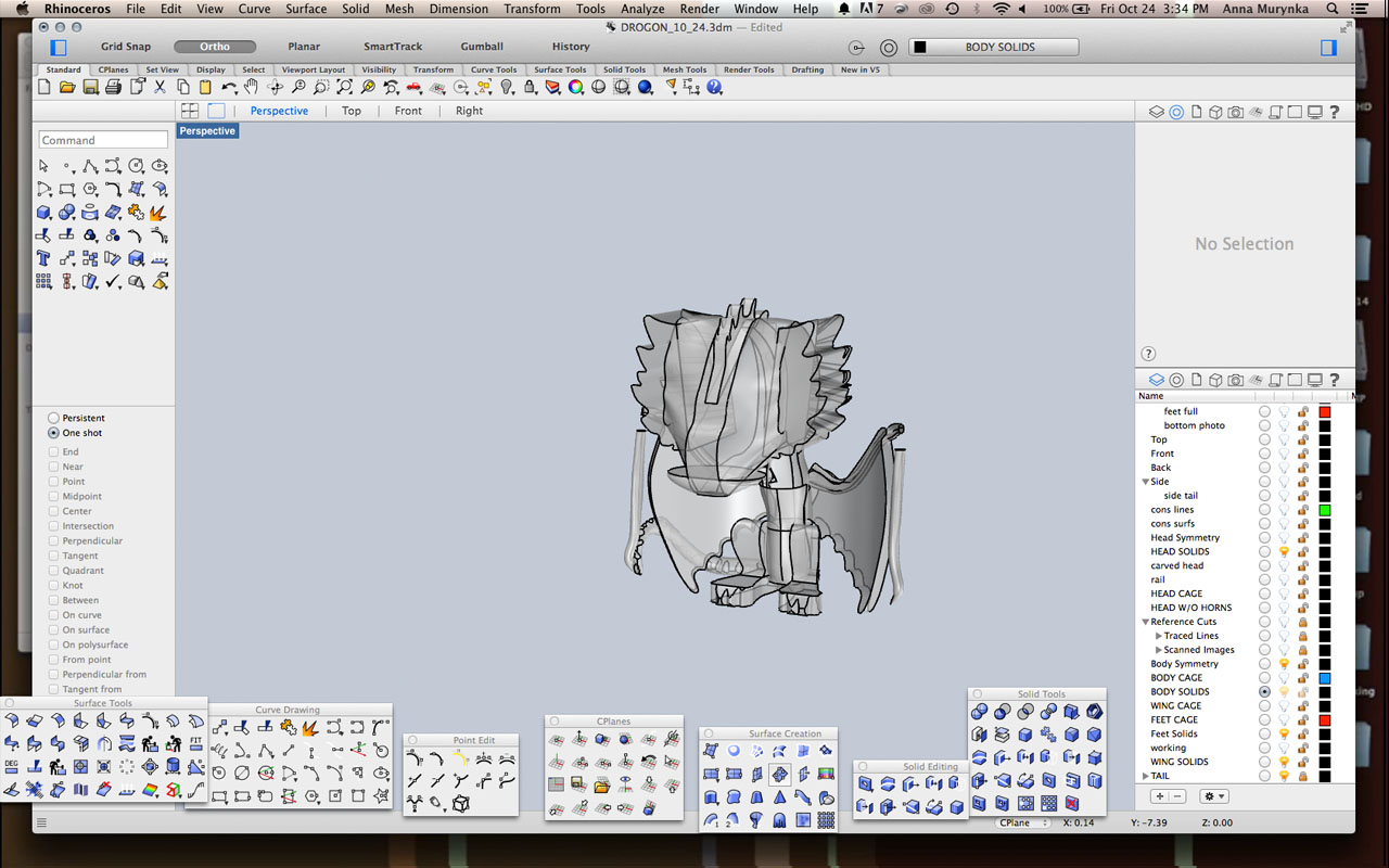
Leanne- Cake is almost done being modelled minus some work that needs to be done on details and creating closed surfaces. In our last post we were experimenting with creating the shape of the body and in this post I will show how I created the extremities and details (mostly commands such as surface network, ellipsoid by diameter, sphere by diameter, sweep2, boolean union, split, join, and by manipulating control points on objects).
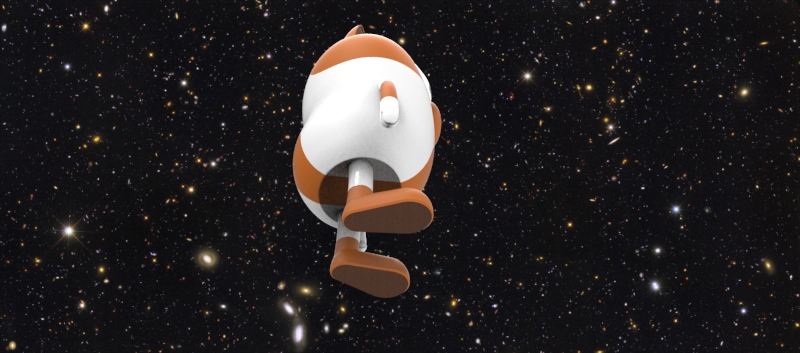
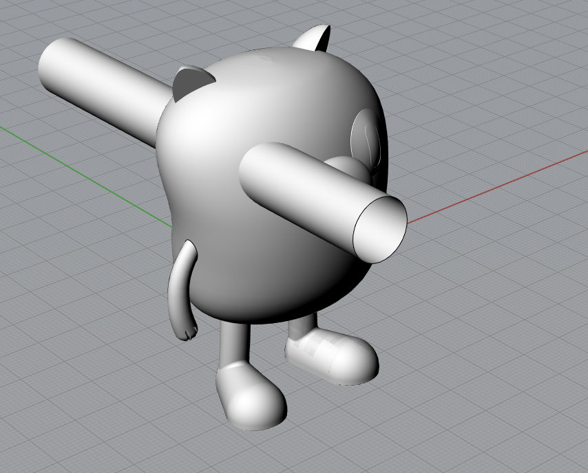
Above is the nearly finished version of Cake.
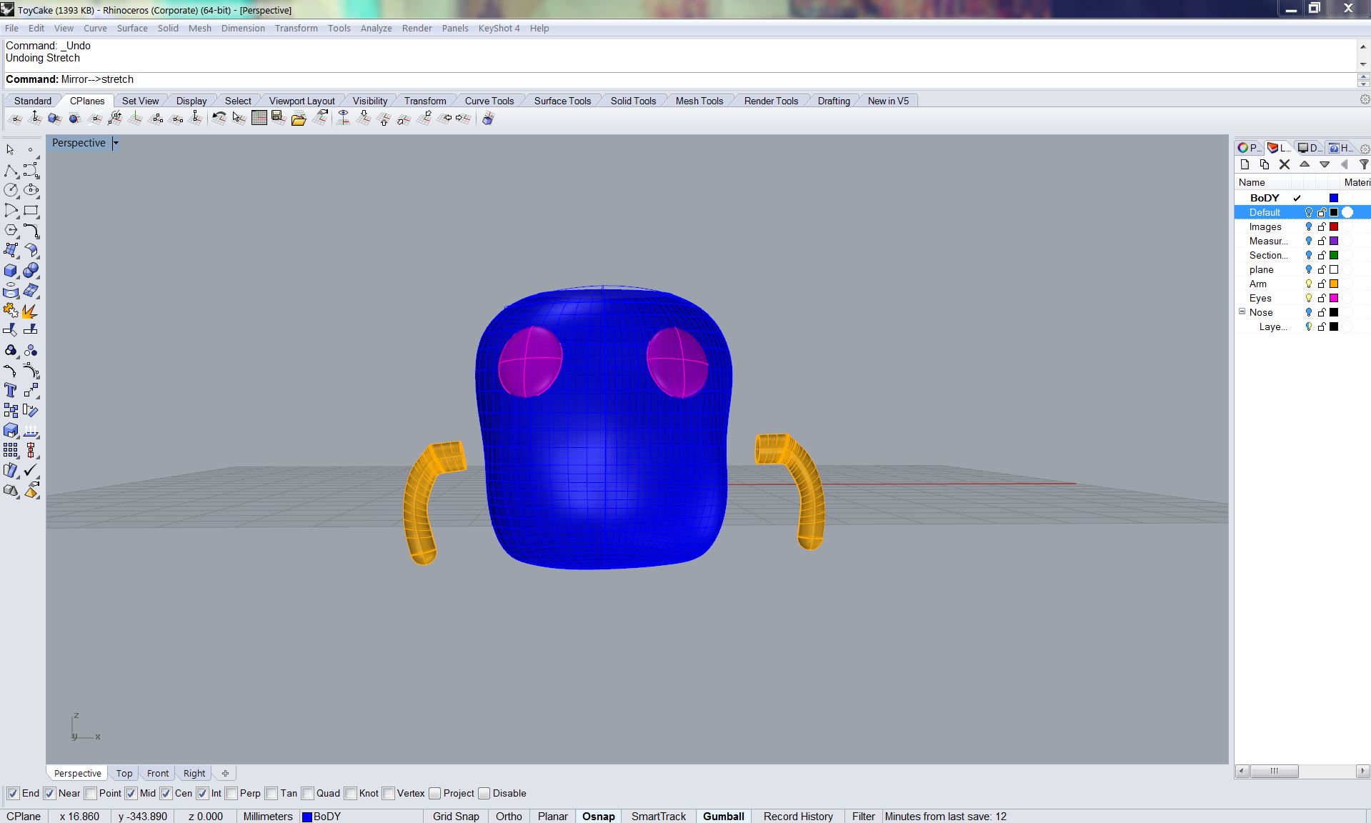
I started with the arms and eyes. The eyes were simply made with the command “elipsoid by diameter.” I took measurements directly off of the doll and made the elipsoids to this dimension. The arms were made by tracing a photo of the front view of Cake. I traced the arms and compared this with measurements directly from the model. I placed an elipse at the bottom of these two lines and did the Sweep 2 command. I then capped the holes to have closed objects.
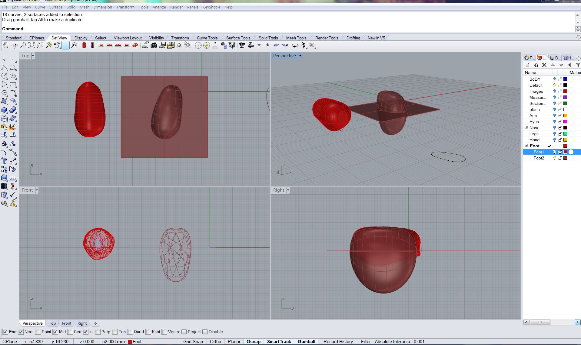
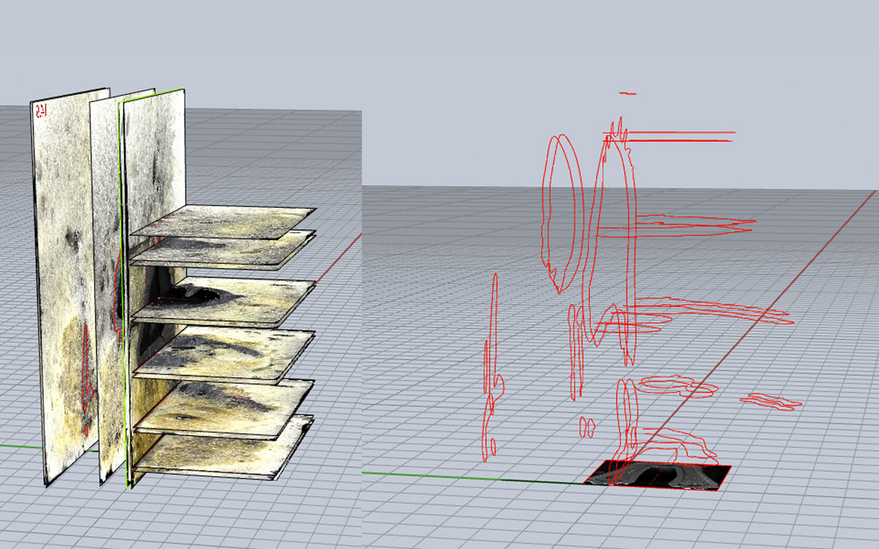
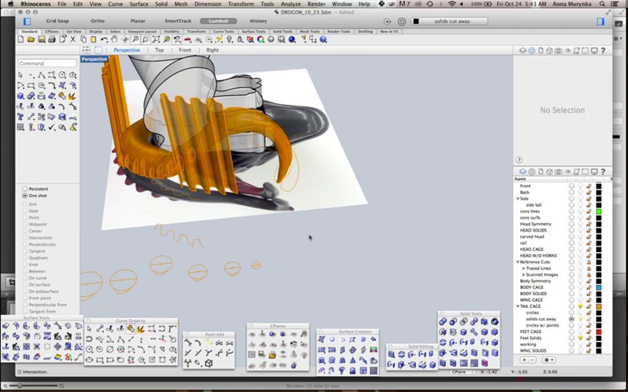
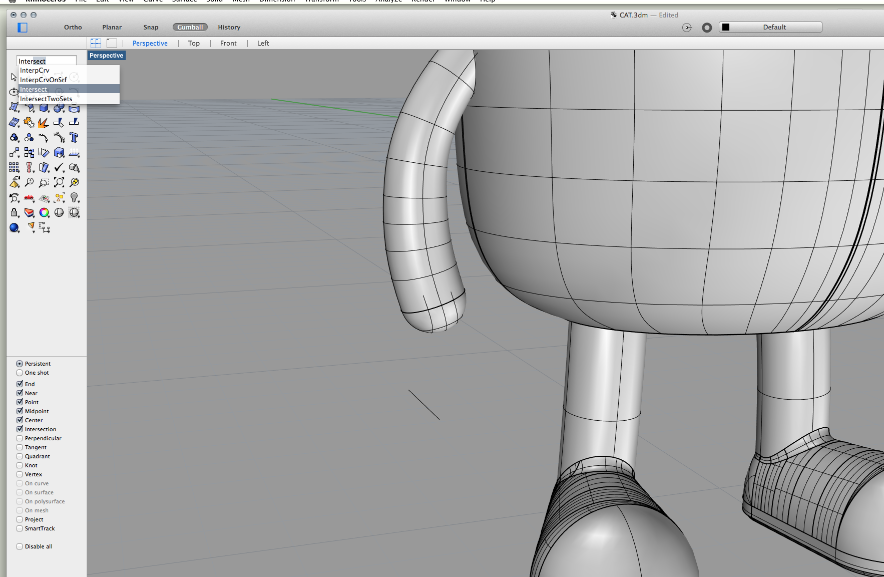
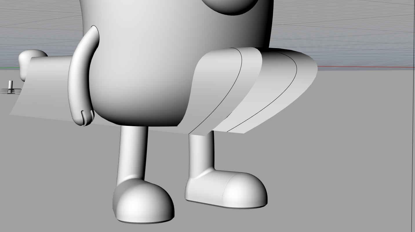
Next I attempted the feet. I struggled with this a little bit. First I attempted a method using thenetworksrfc command (the brighter red foot on the right). I traced the shape of the bottomof the shoe off of the model, then created a wire frame of the shoe based off of photos and measurements. It was really hard to accurately measure and I realized I was getting too detailed. I was getting tired and the foot came out really terribly. I decided to try a new method. This was to manipulate control points on an ellipsoid. I manipulated them to match up with the actual footprint of cake and the outcome was much better than the first. I trimmed the new shoe with a plane (as you can see in the photo) and then capped the object.
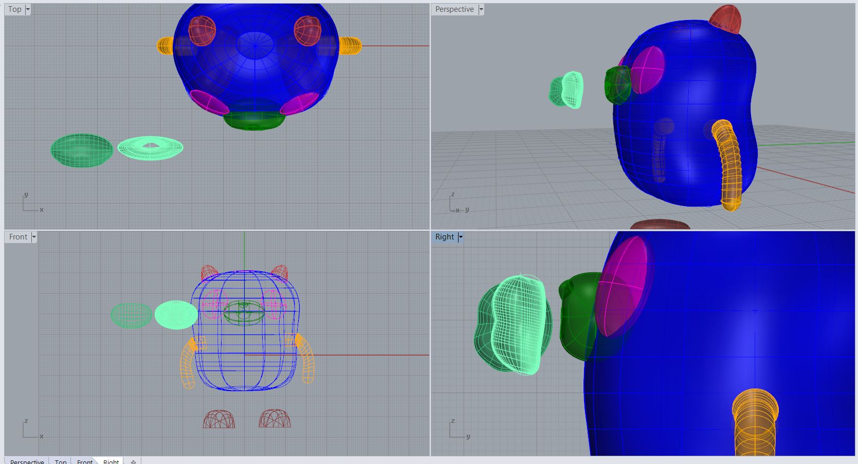
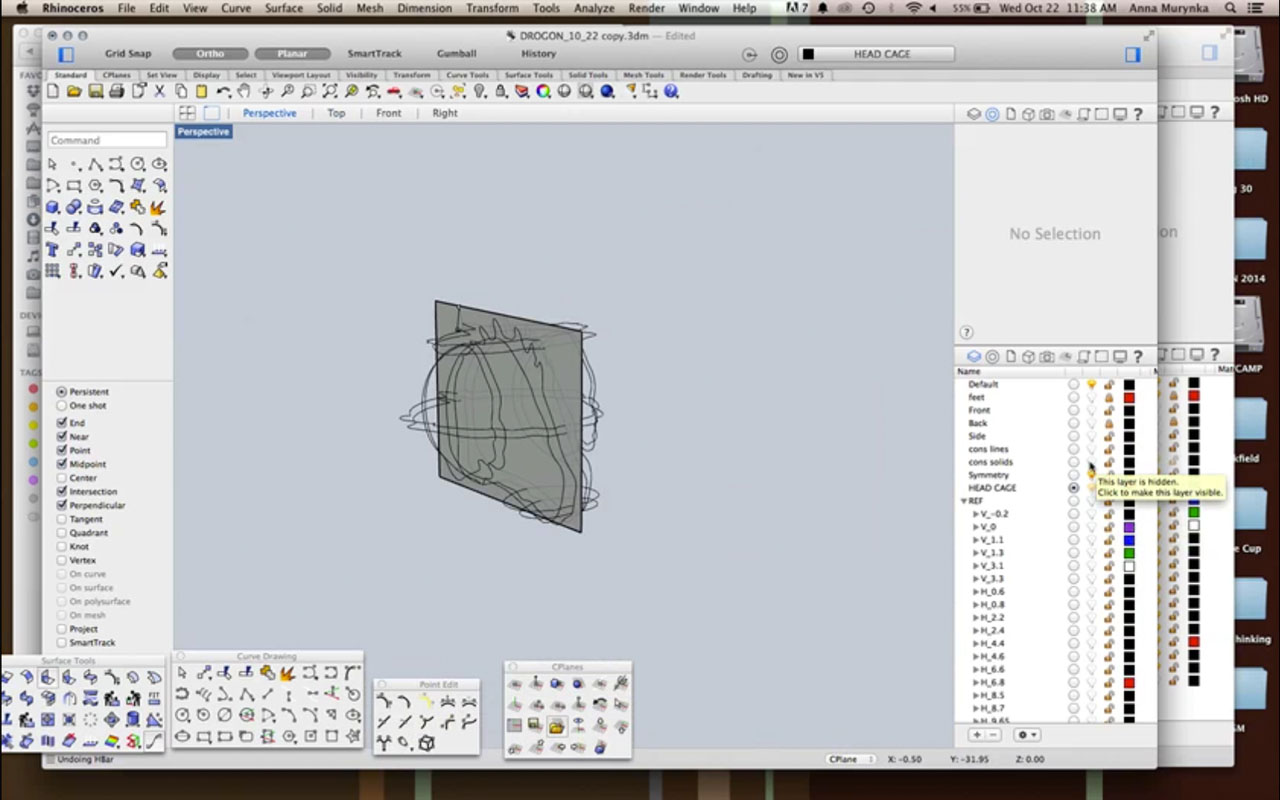
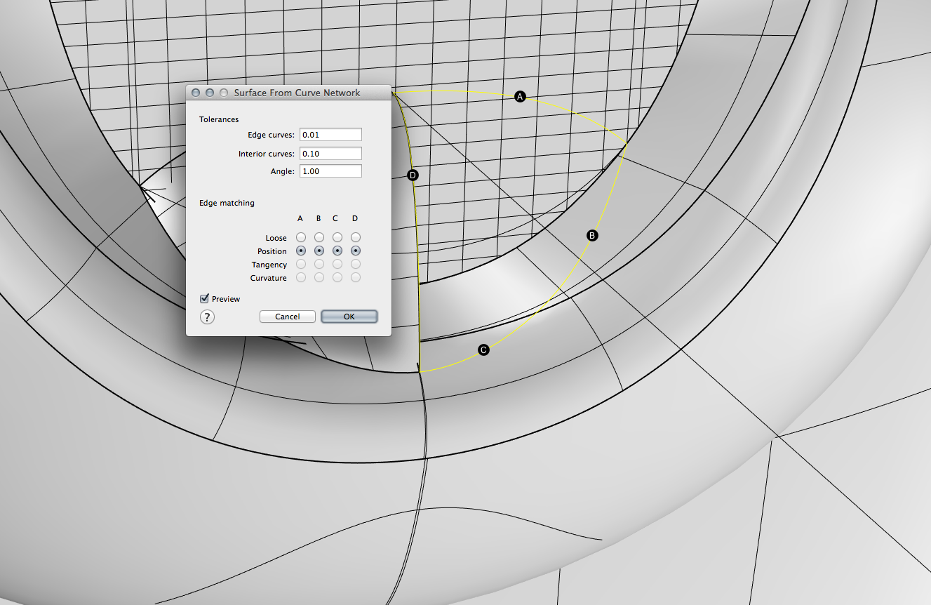
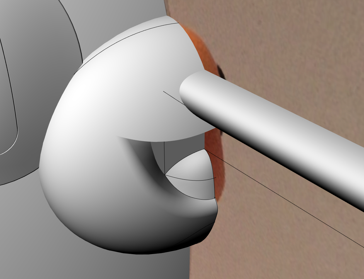
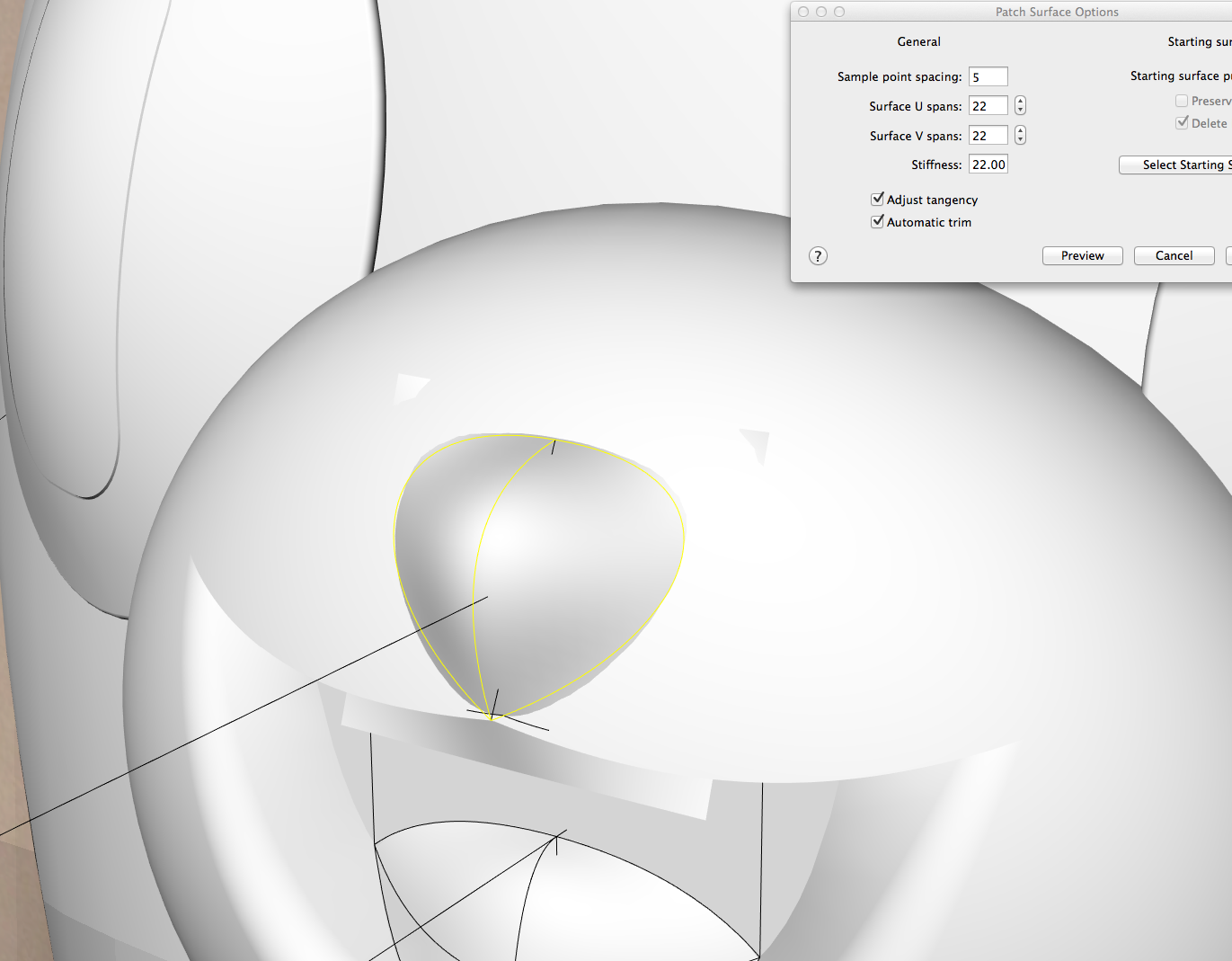
Finally I worked on the nose. It took a few tries to get it right. The first attempt was to manipulate control points on a sphere. The second was to take the profile, use photos and measurements and create a wireframe to run the networksrf command with. This did not work for me. It was too finicky and a waste of time. I ended up going back to manipulating surface points to get a desirable outcome. I did the same with the tip of the nose and have yet to figure out how to join these to objects.
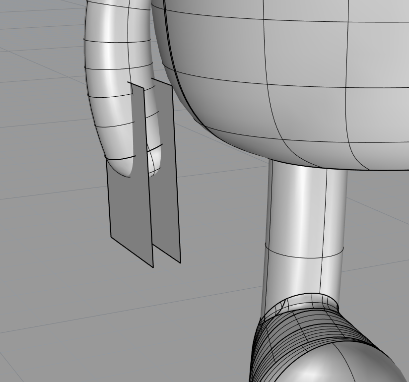
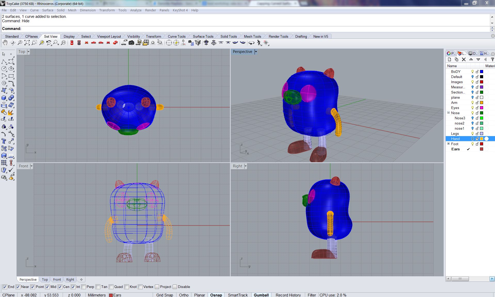
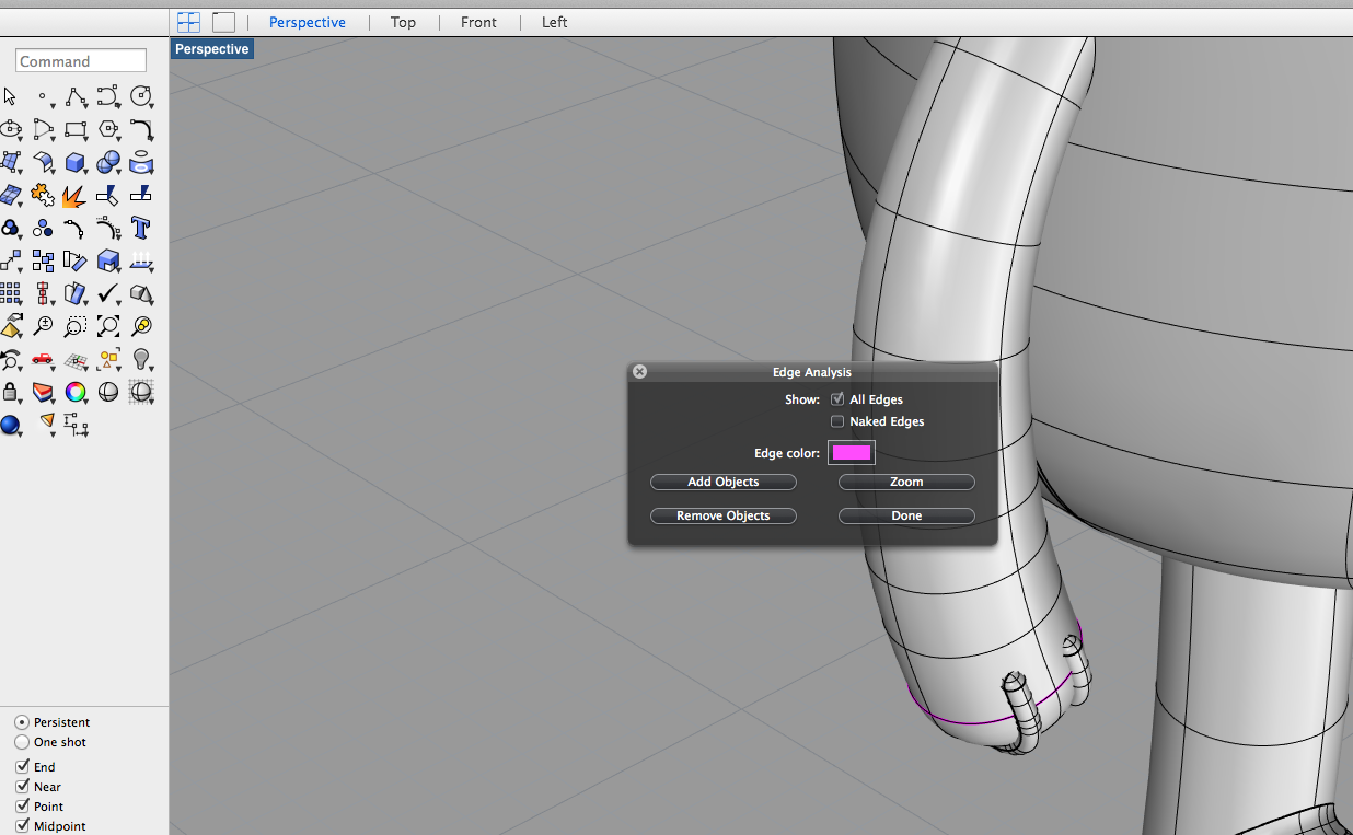
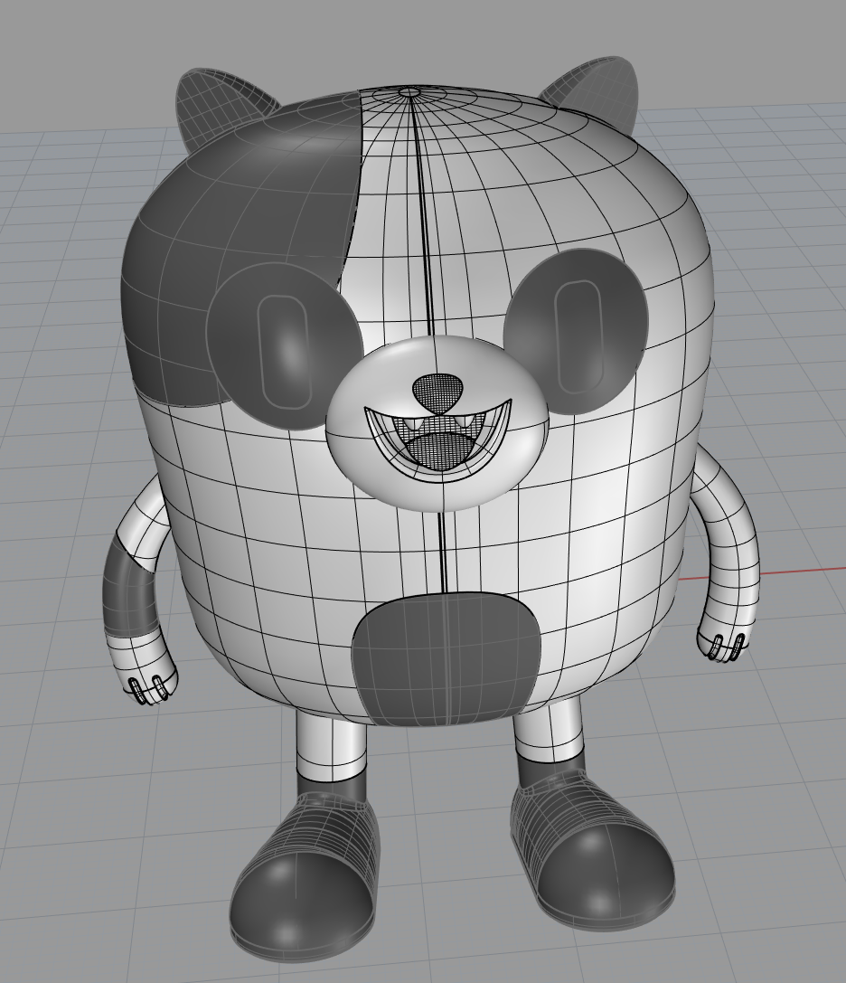
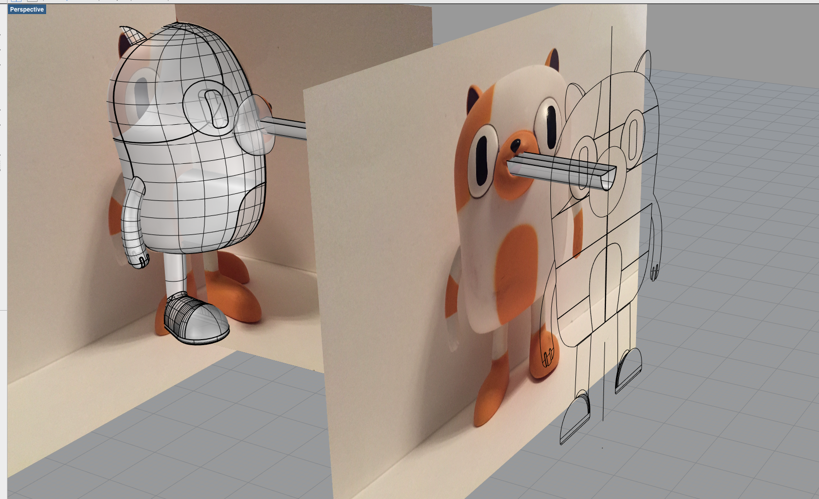
Viktoria – My approach was to combine tools like pipe, surface curve, patch, loft. I ran into issues in making the fingers – I attempted to pipe separations and then split the difference then fillet to smooth them but the effect was not entirely successful in making the hands accurate to the actual object. I also had to reconsider some approaches when I considered the rendering requires, so make separate pieces that would be the different colours of the model. To make the face I traced the eye in front view from the photo then extruded through the torso booleaning difference to create a circle that warped to the contours of the torso then making surface curves to create the shape. I had initially attempted to create the eyes using spheres but found that method inaccurate and harder to control. I will rework the facial details in my next iteration for further accuracy and fidelity. This current model is not ready for 3d printing yet as it is not water tight – there are some ‘messy’ bits on the inside that need to be cleaned up and edges that need to be closed.
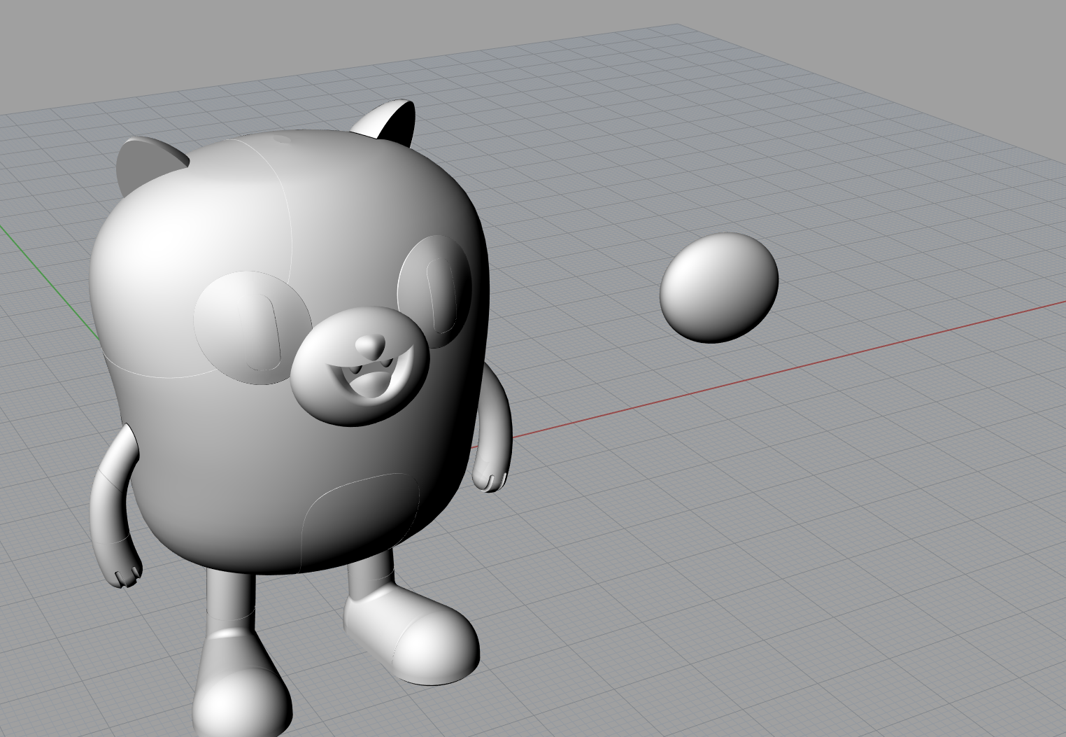
In playing around with my renderings I had a few different approaches – I used matte paint materials for one model and metal paint materials for another. The matte version (though more like the actual model) came out looking dull in the render. The shinier metal paints gave the rendered model more dimensionality and liveliness but is less true to the actual model. I also realized in rendering that I am missing an orange arm patch on one arm, and that the back of the mouth/throat needs to be separated in my Rhino model so that I can colour it separately
l