Tag Archives: rhino

Studio Rendering Update

I’ve been preparing my rhino files to bring into Keyshot. After a few test runs, I’ve developed some strategies:

-Placing different elements of the structures on different layers as to prepare the ‘inside’ and ‘outside’ Keyshot renders,, in order to later insert people into the structures between separate photoshop layers.
-Importing my backgrounds into Rhino via Picture Frame as to play around with the angle I’m planning on rendering; this makes preparatory layer organization of ‘inside’ and ‘exterior’ easier as well.

Screen Shot 2014-11-30 at 11.22.31 PMScreen Shot 2014-11-30 at 11.23.13 PM Screen Shot 2014-11-30 at 11.21.07 PM Screen Shot 2014-11-30 at 11.21.58 PM

Finn the Human: Printing, Documentation, and KeyShot… (FINN)ALLY

(Finn)ally, the time has come! 3D printing, at last!

I printed using the clear filament and let me tell you… It’s good perhaps for test prints but I would never want to use this to hand in any final model! The second print with white filament has much better resolution even though the file was exactly the same.

In order to print my second model quicker than the first I detached the head and changed the body orientation. In the future I wouldn’t rotate the body- having the belly down meant a rougher print. Moving forward I will always try to orientate my model to have the least amount of struture material BUT keeping the bottom at the bottom so that the rough print is not visible.

KEYSHOT:

A really simple rendering tool! I enjoyed the selection of colours and materials available AND the edibility of those (saving them too).


(One tip I’ll leave here about the Tinkerine 3D Printers that we have access to… We should make proper model files BUT when printing with these printers you don’t have to close the surfaces! The pink lines are not the end of you!! The resolution of these machines is not precise enough to require that last step.)

Screen Shot 2014-11-17 at 12.05.51 PM                split finn

Finn the Human: Surfaces, (Finn)ally!

Now that I’ve finally figured out the best way to go about tracing this little dude I have surfaces! I used a variety of surface commands- depending on what existing lines I had for the particular surface I wanted to make. We’re all familiar with the usual suspects, so I won’t bore you, but my favourite commands for a few details and which came in handy were “Pipe” combined with “BooleanDifference.” This combo was great for details of clothing or things like hands! Mostly at this stage the different commands I used were trial and error until I figured out what worked. I also watched a few different surface creation tutorials and followed along to get a handle of the different commands and when to use them. During this stage I:

-scaled the images and assigned a layer                                                                     -positioned the images to the correct view                                                             -traced the toy at it’s different views                                                                           -surface creation                                                                                                                      -“edit control points” ON and adjustments made where applicable


finn model snip

Zero Vinyl Toy Final Progress

Zero-made-of-Glass

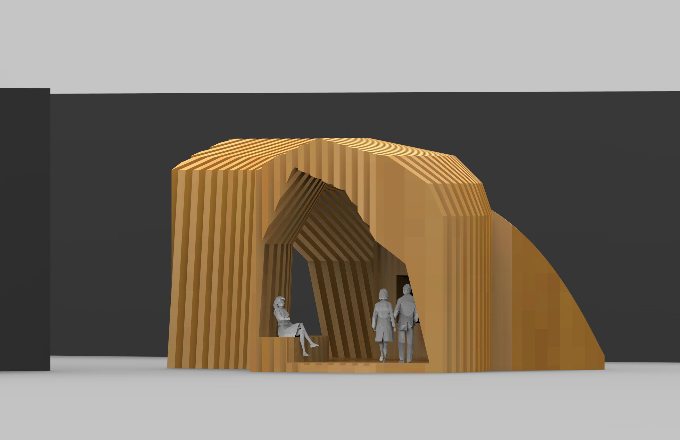
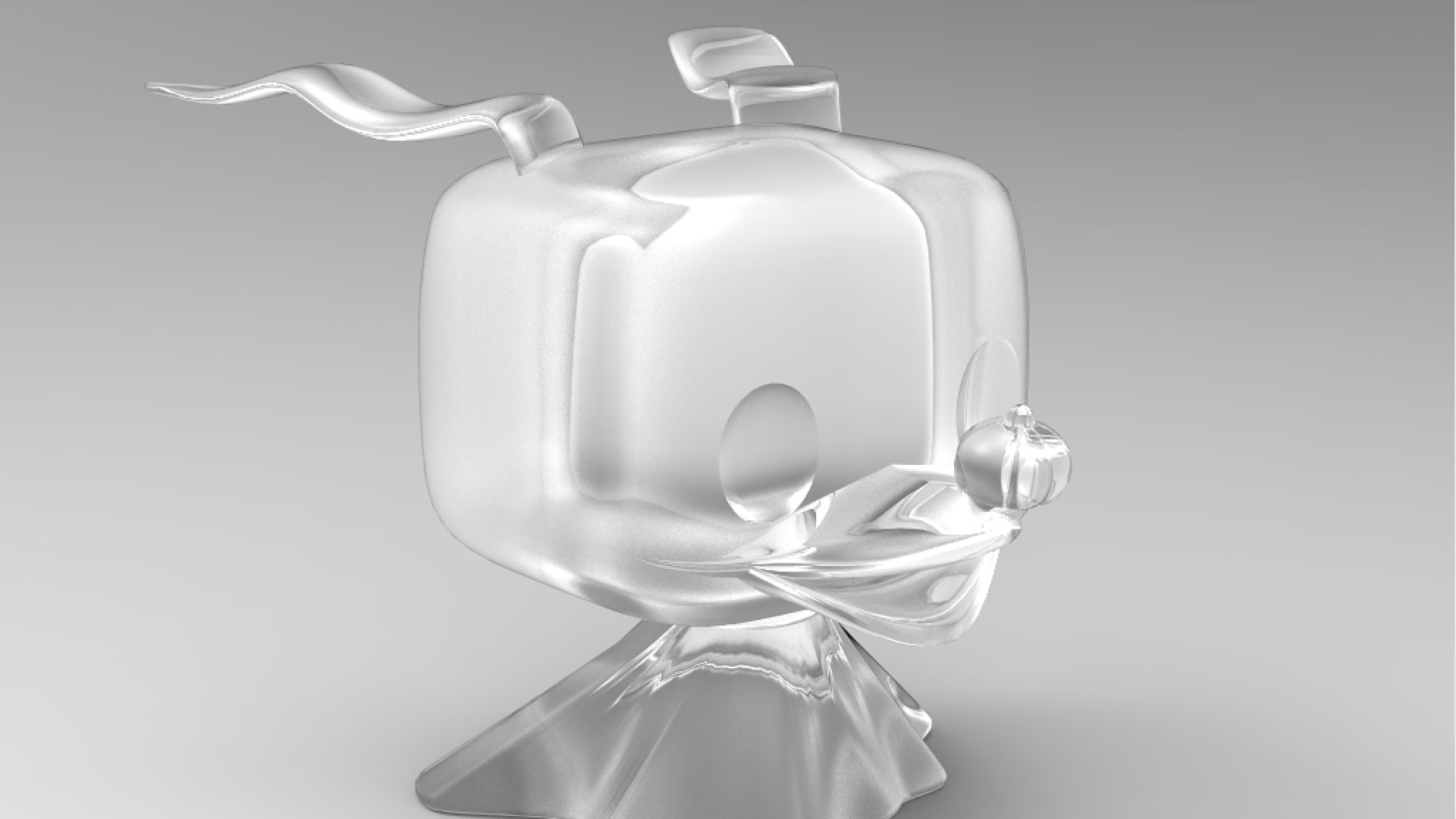
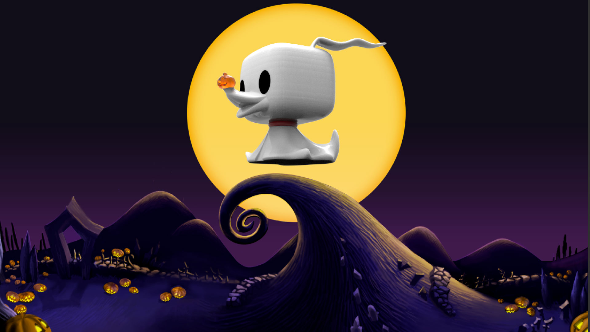
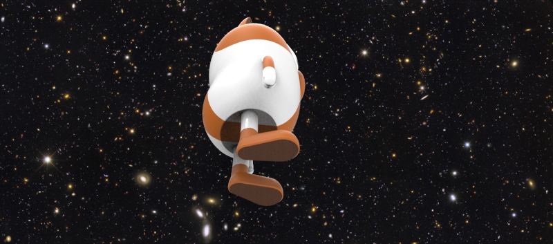
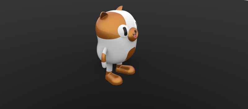
Before continuing to model the body, I had fun trying out Keyshot!

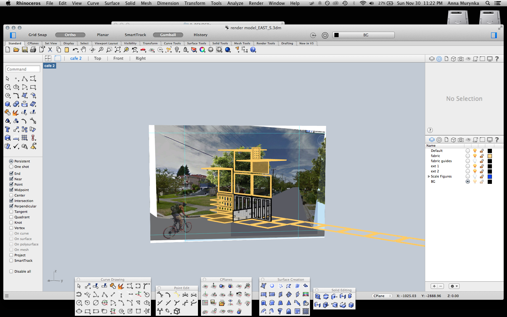
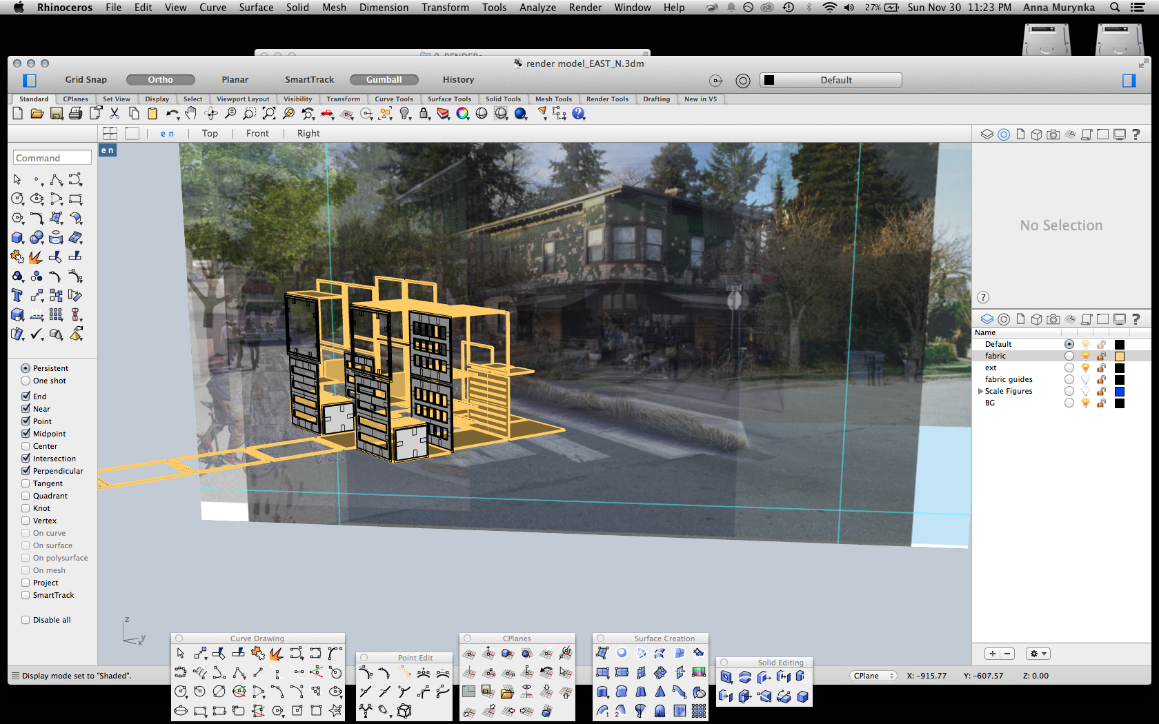
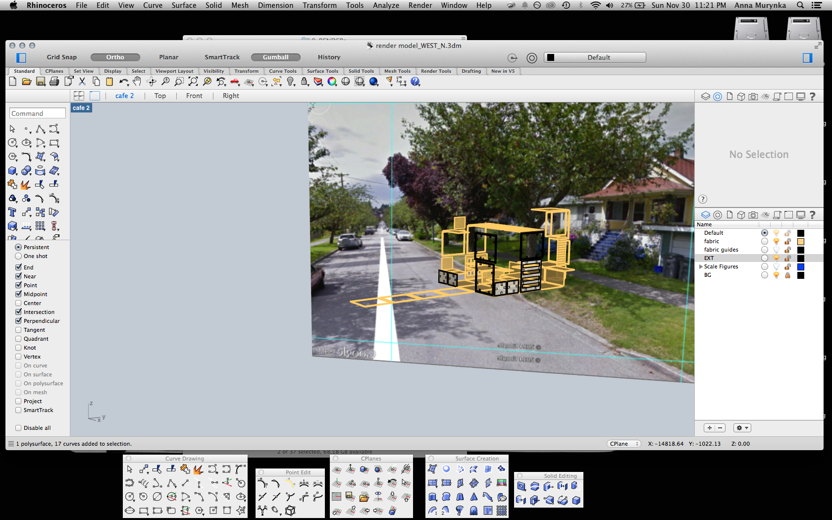
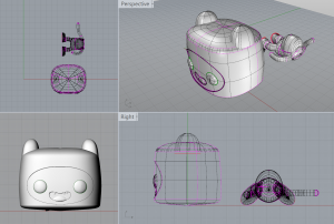
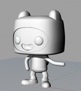
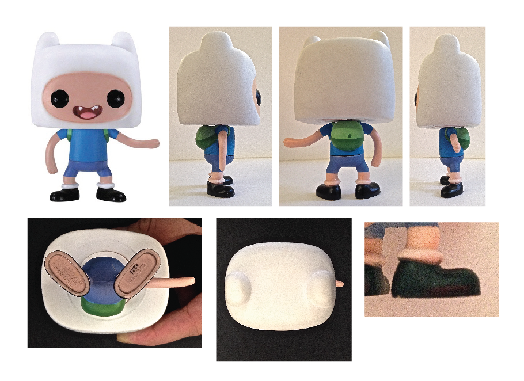
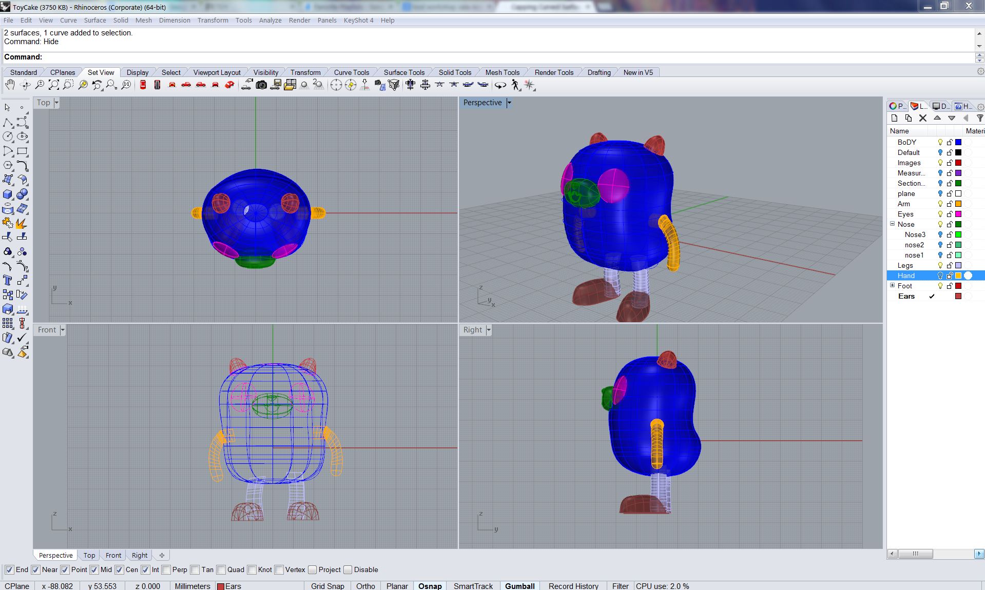
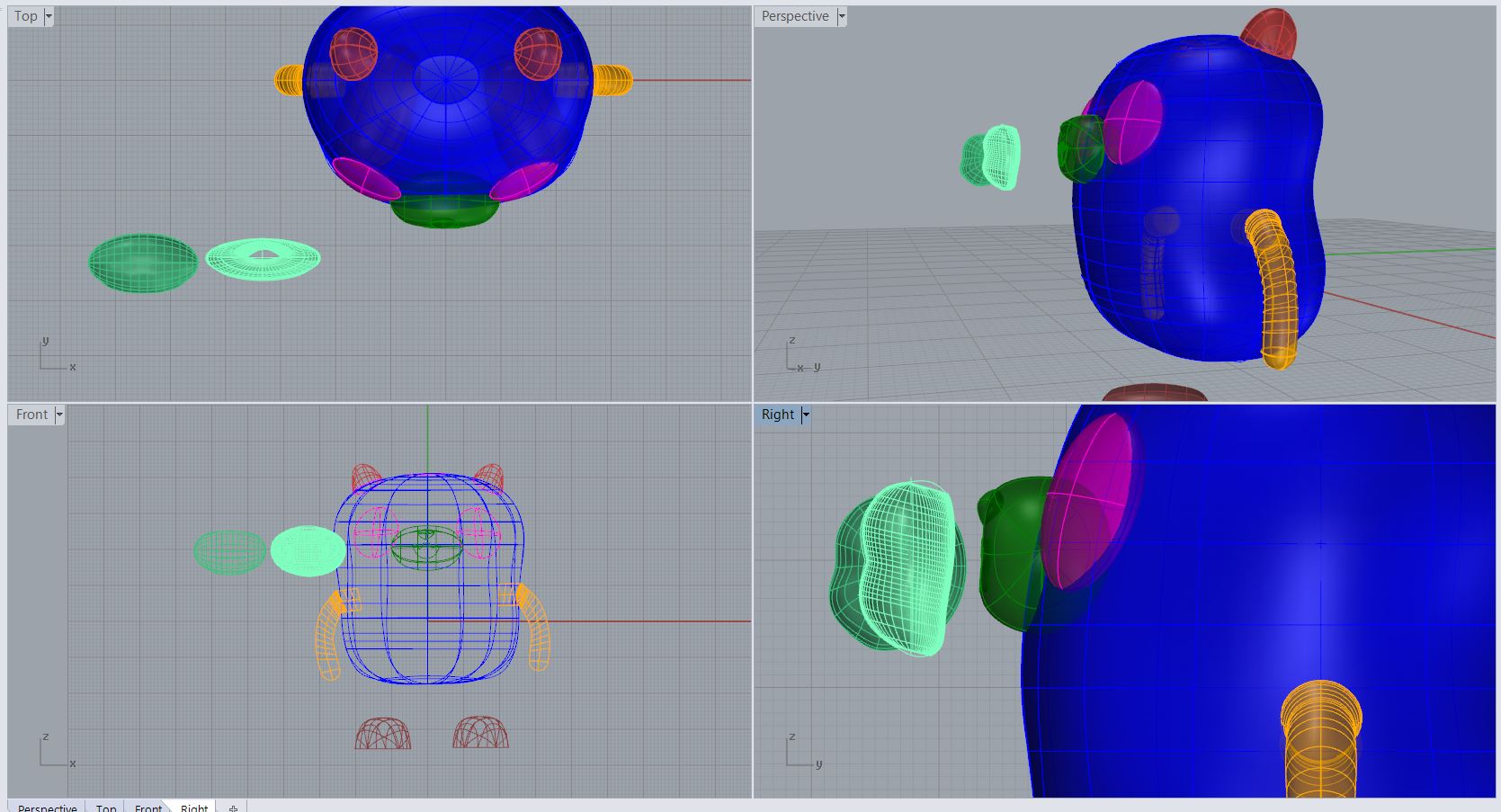
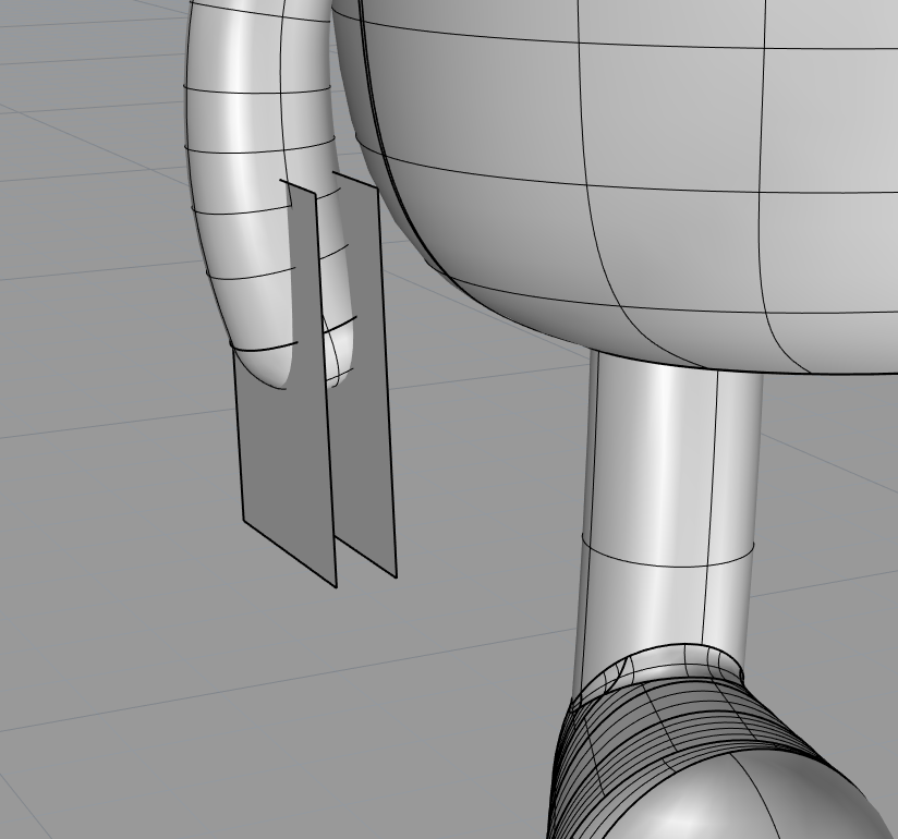
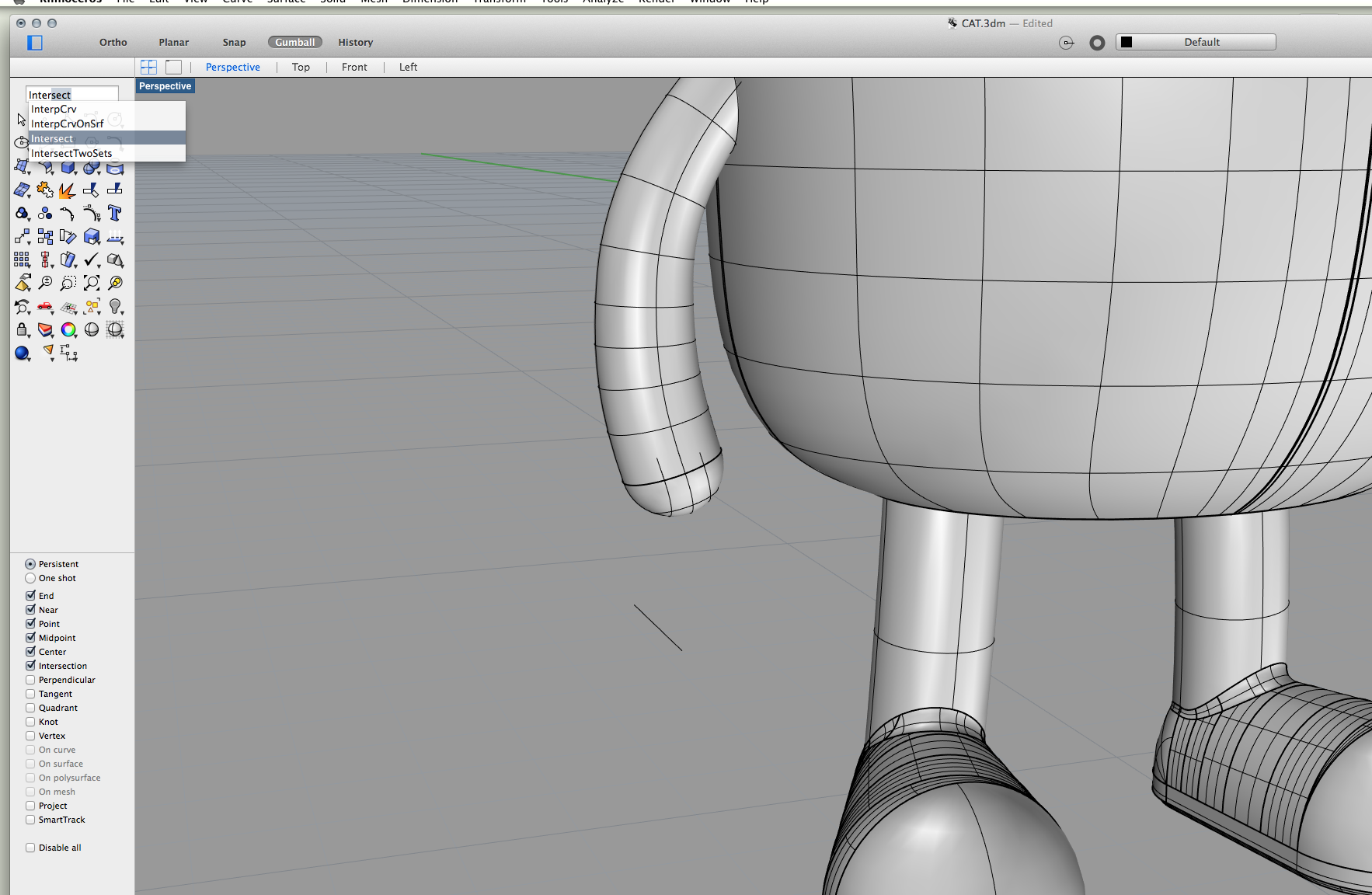
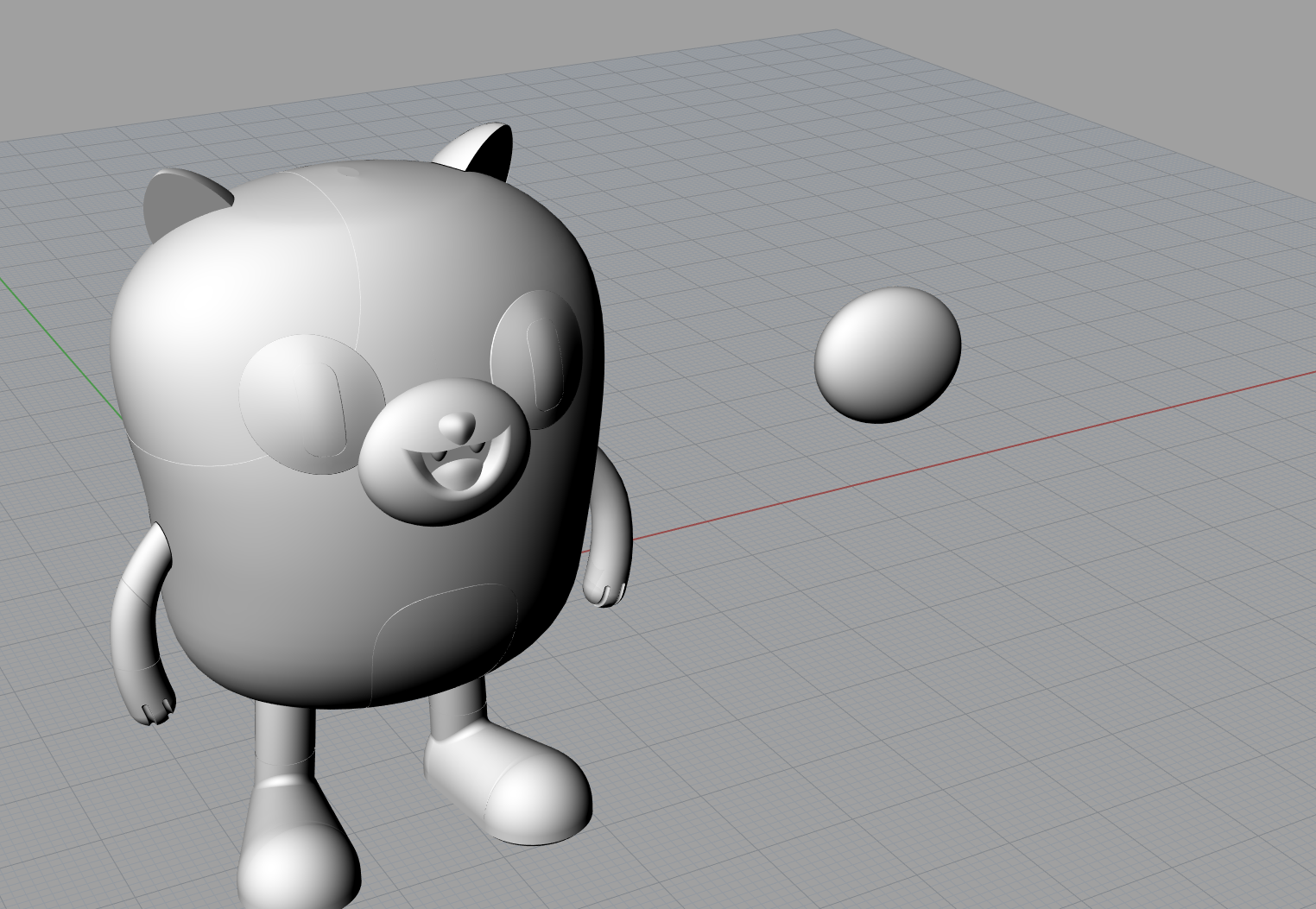
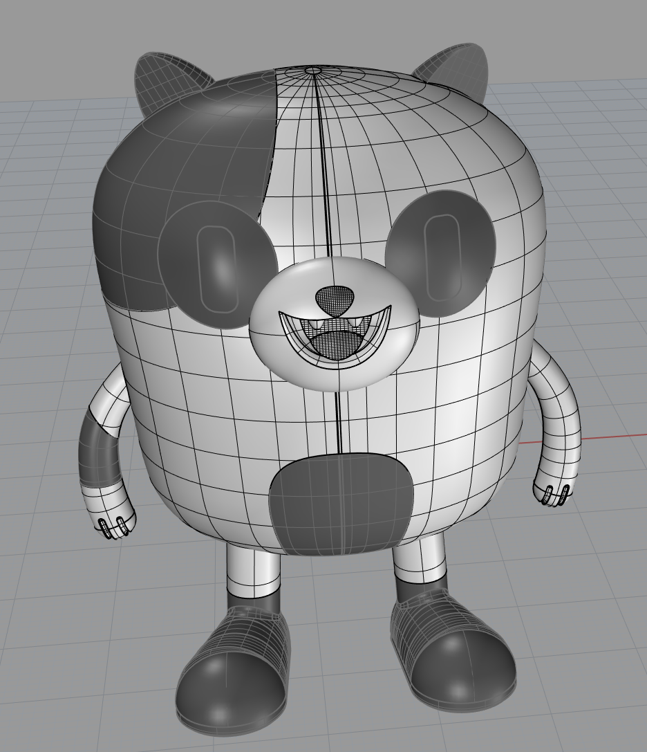
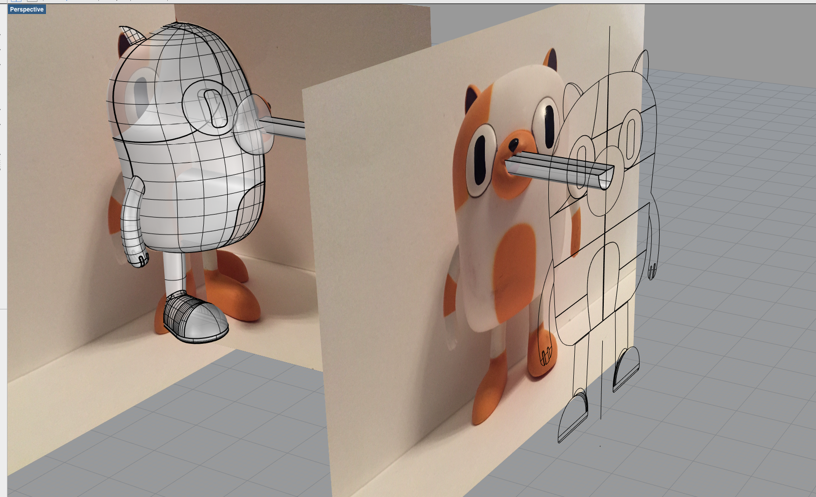
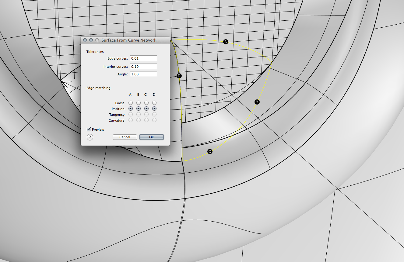
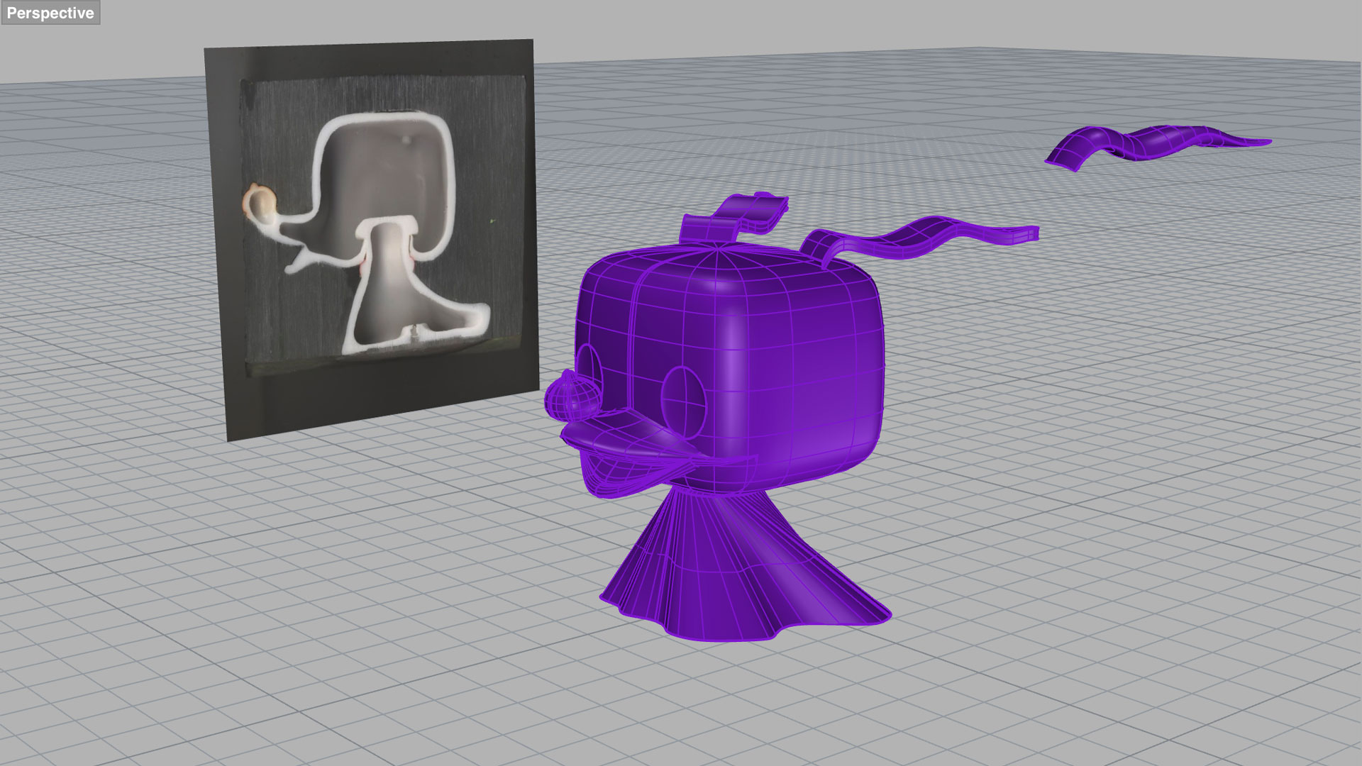
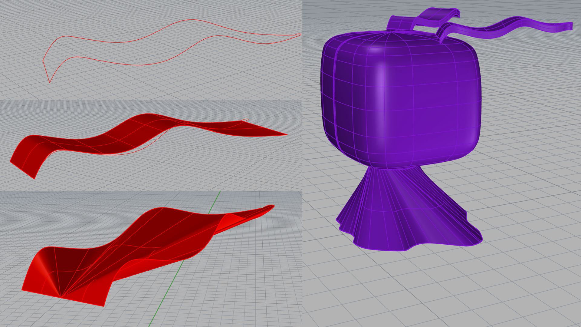
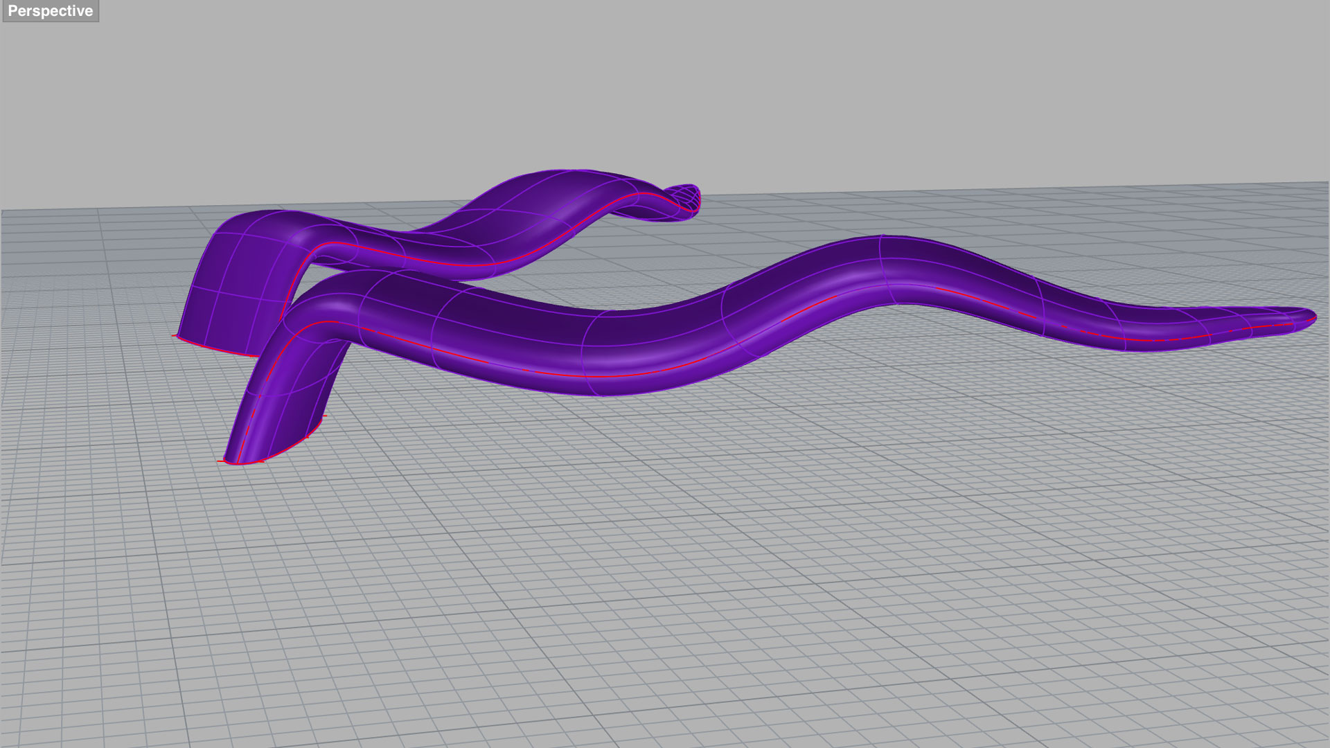
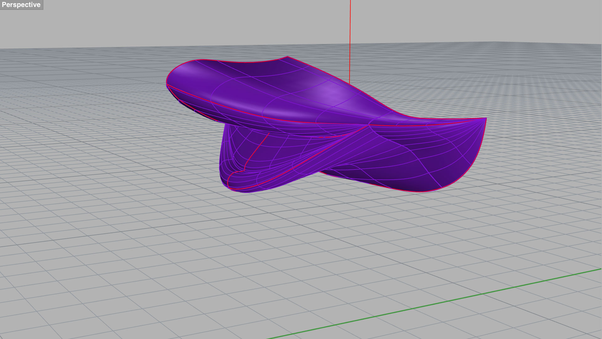
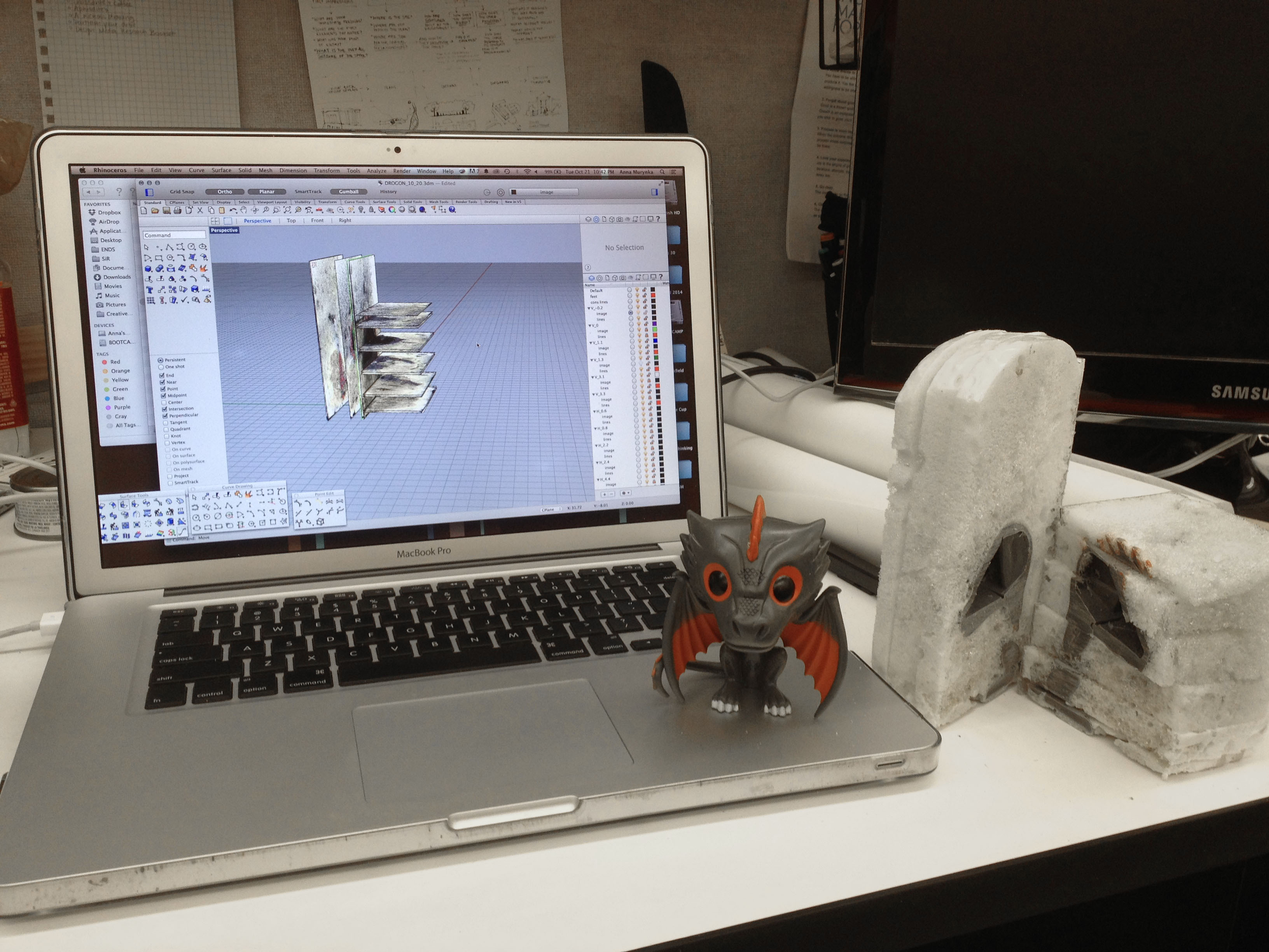
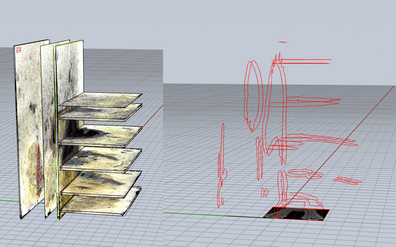
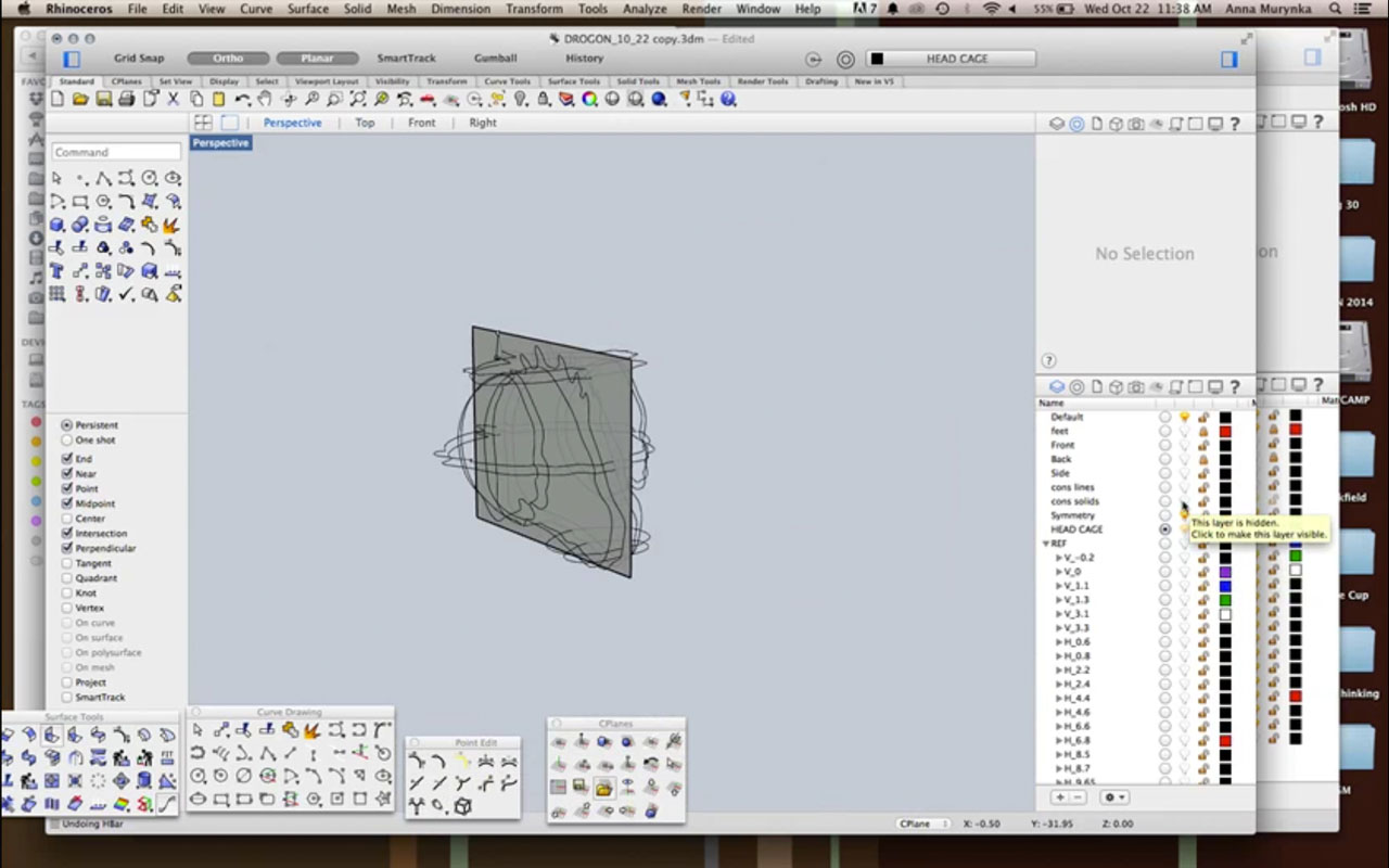
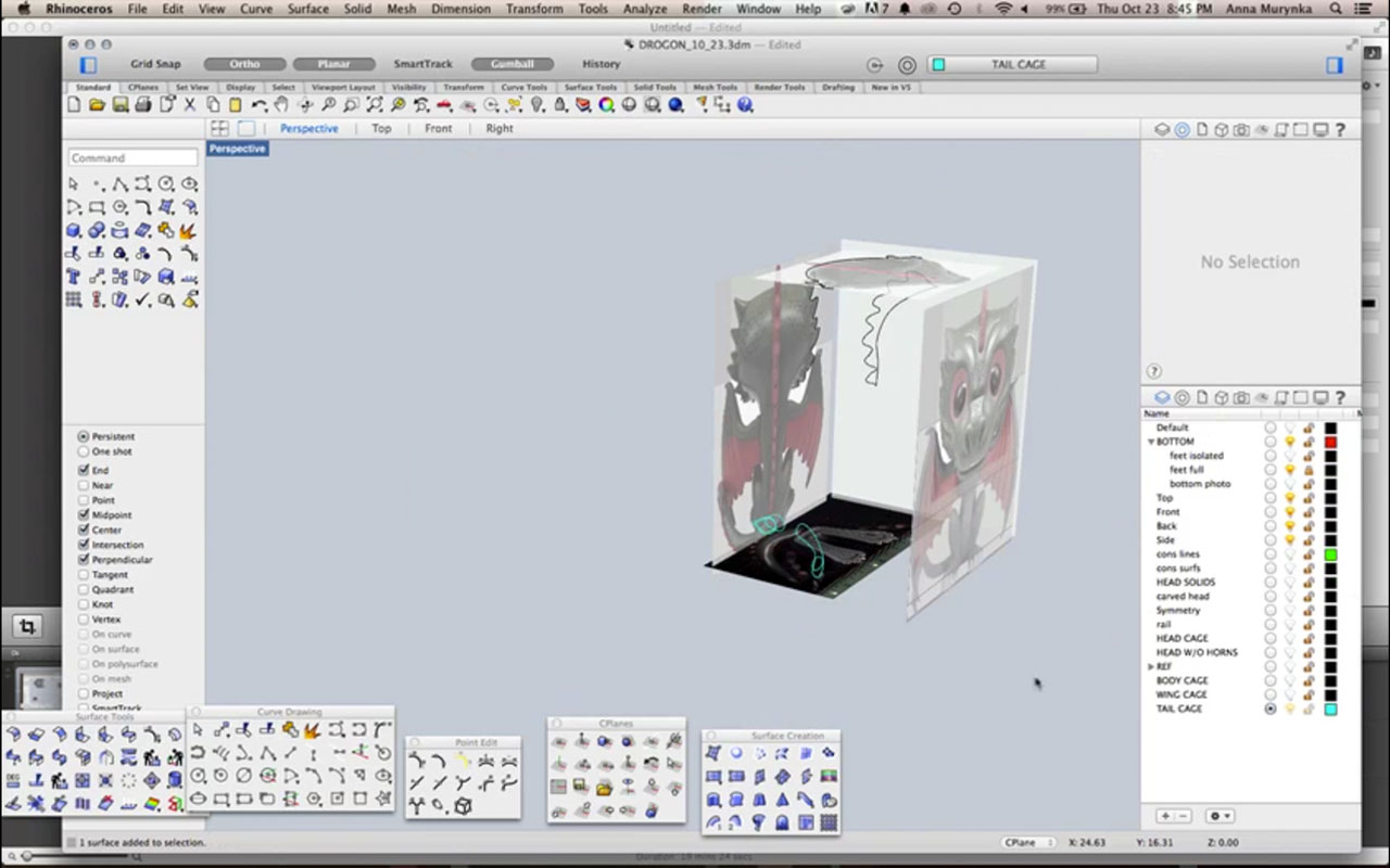
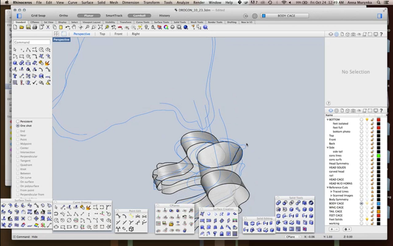
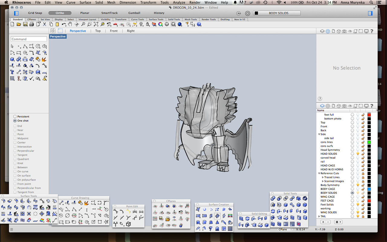
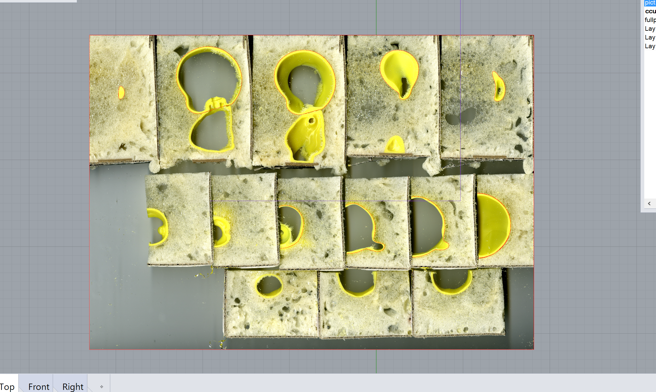
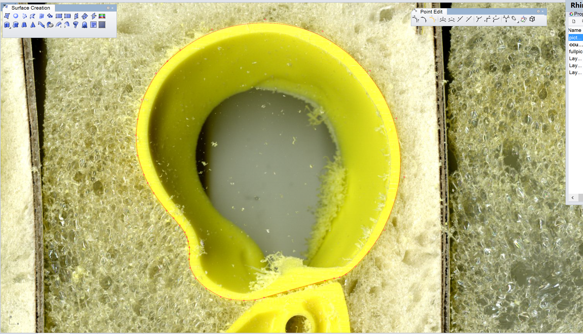
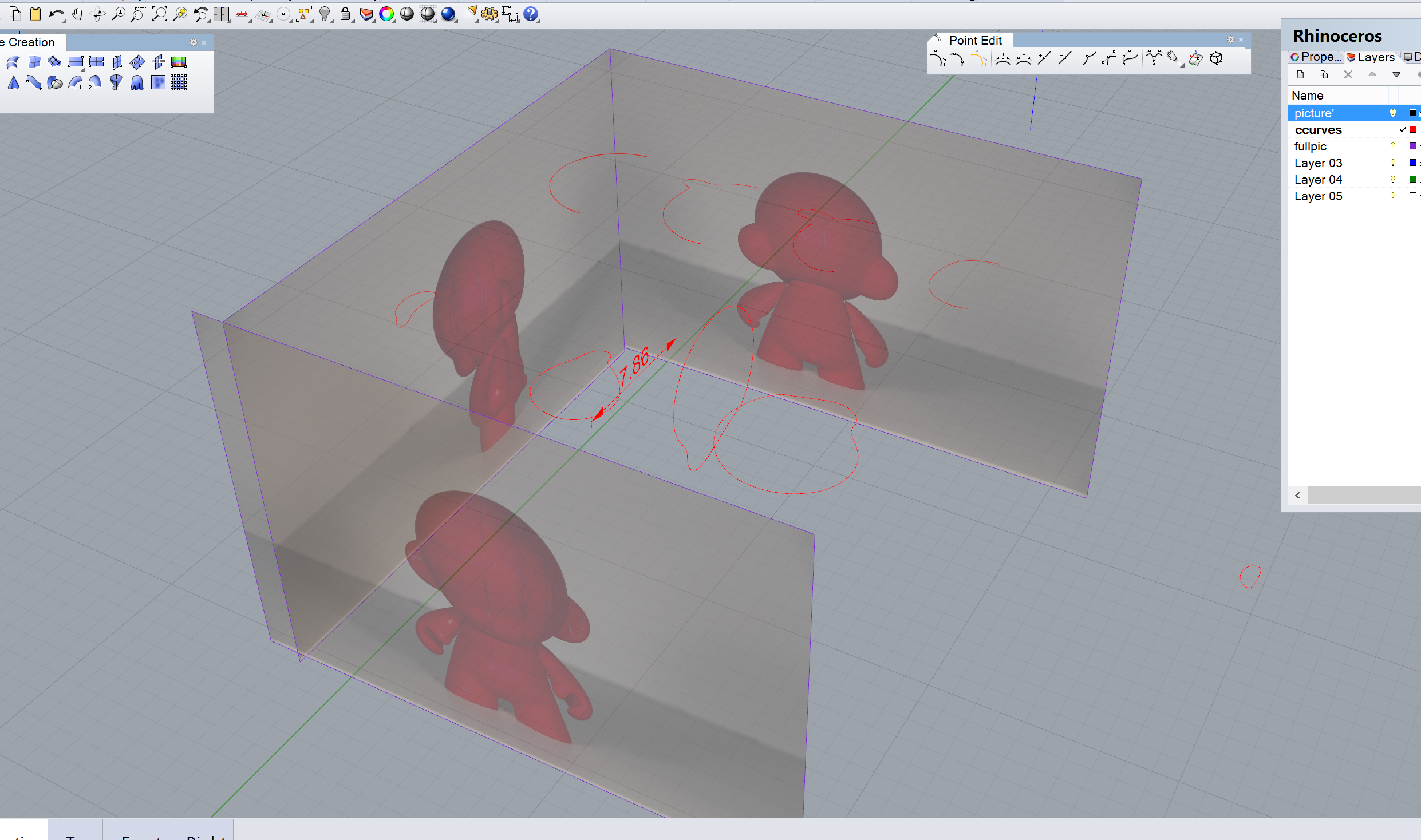
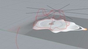
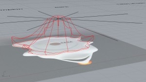
In order to model Zero’s body, I used the photographs and one scan to create reference lines, and tried many different commands such as Loft, Sweep2, Rebuild command, and NetworkSrf to connect the lines into a surface. NetworkSrf produced the best results, but needed more reference lines than I had expected.

29-oct-body-frame zero-guidelineszero-body

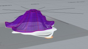
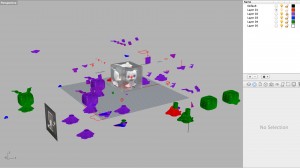
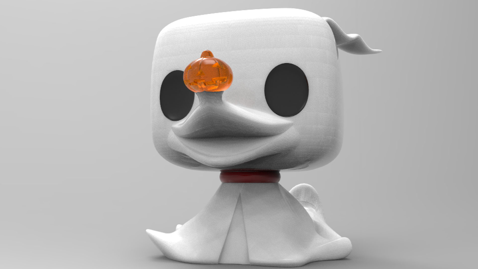
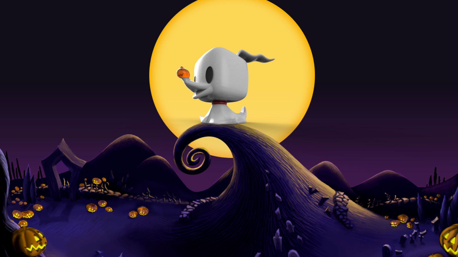
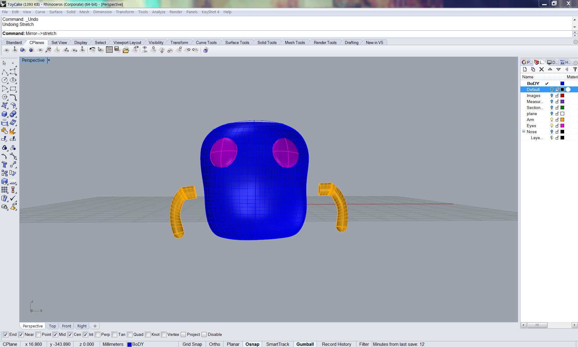
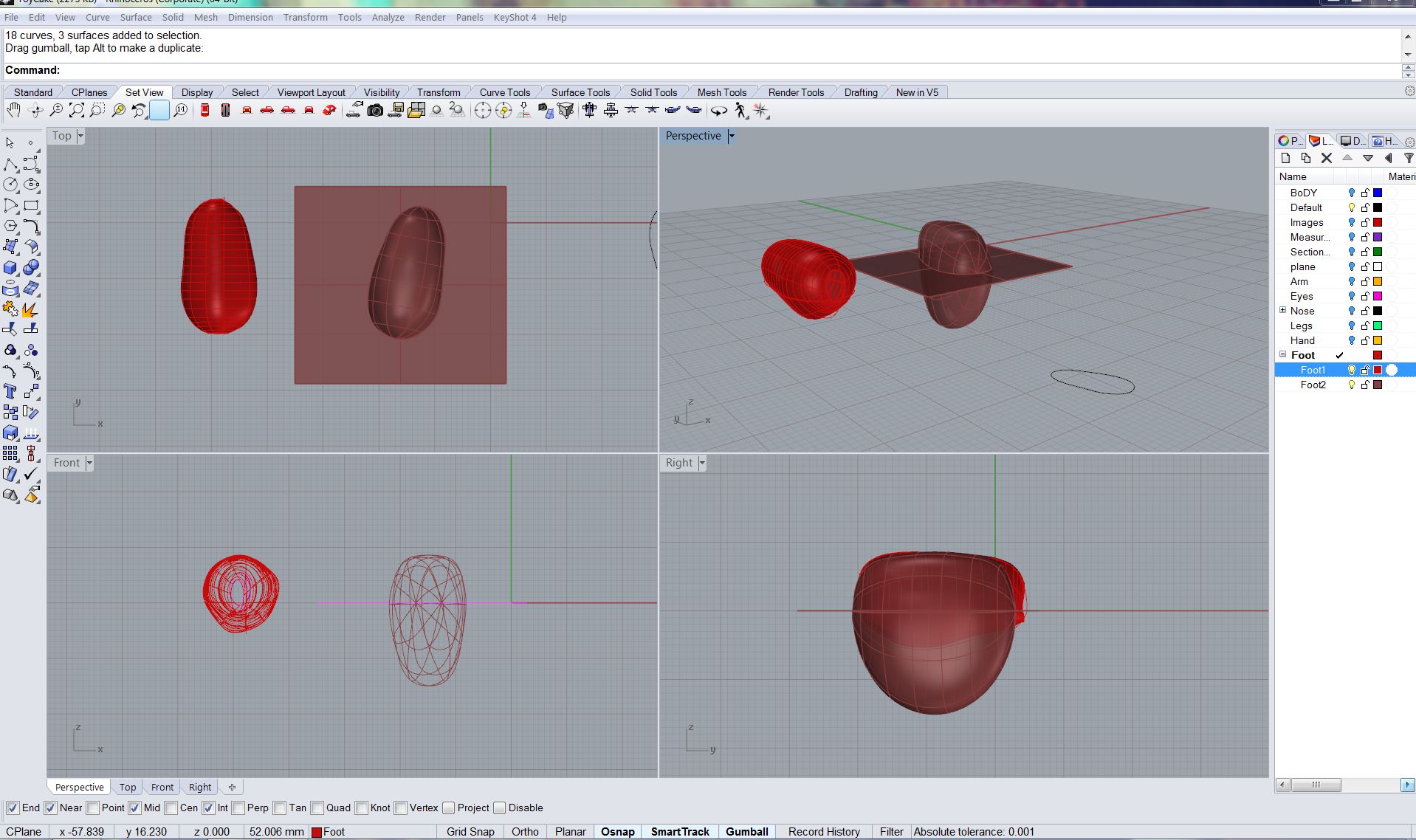
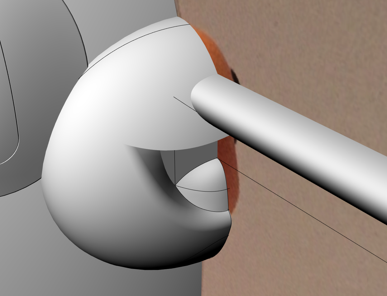
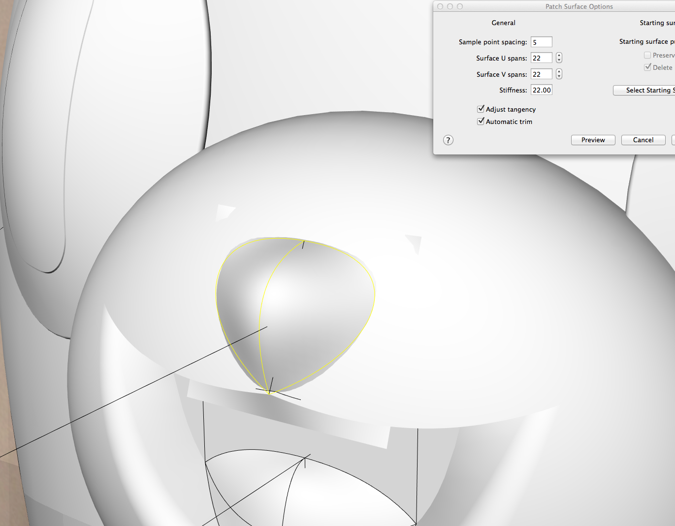
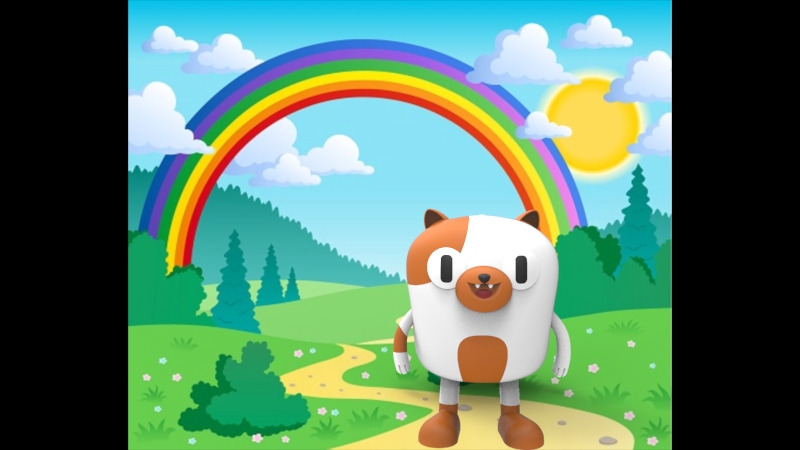
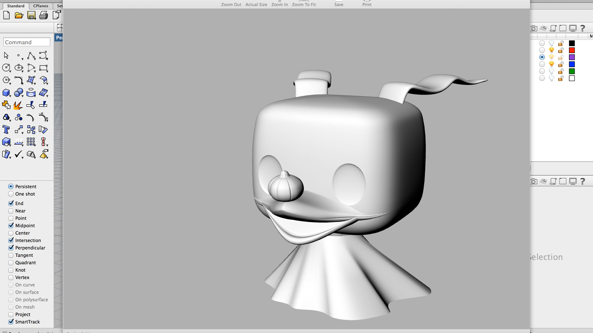
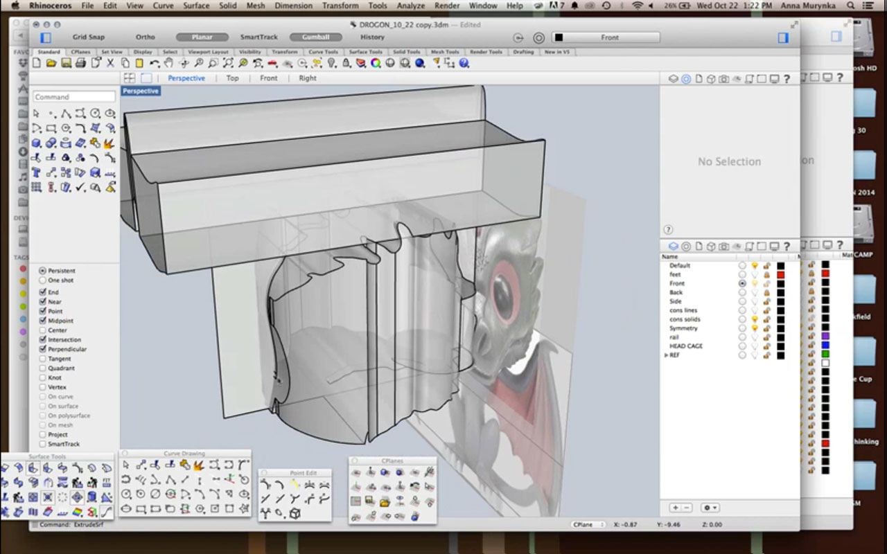
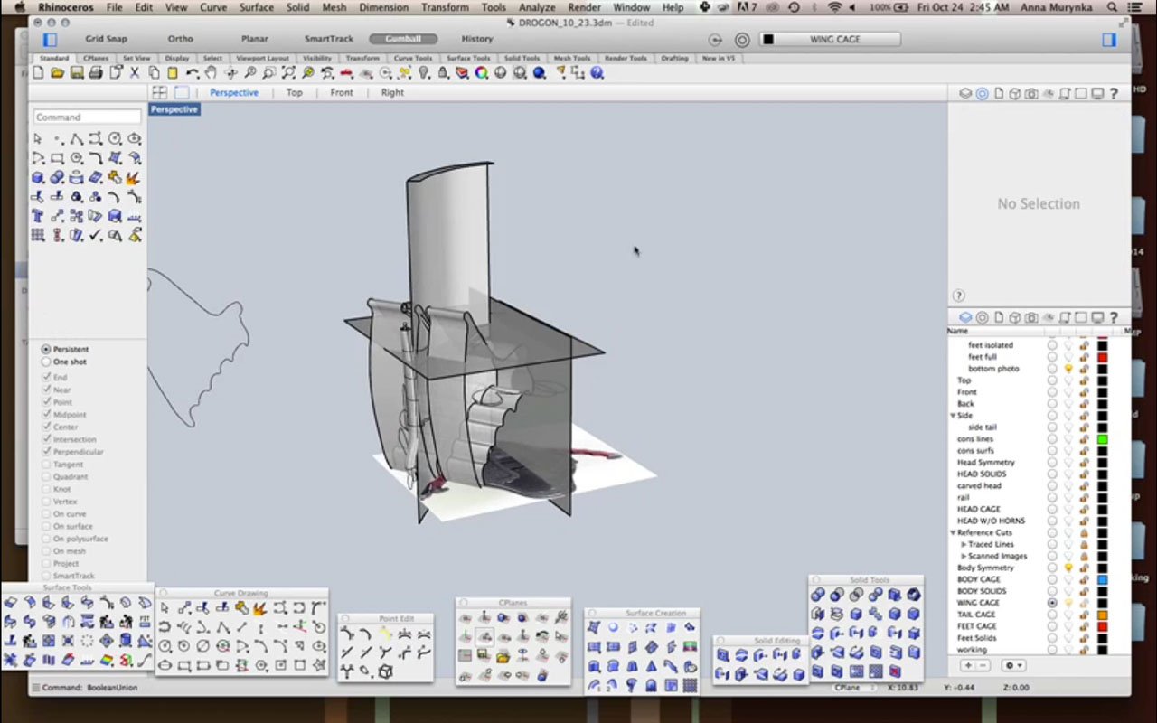
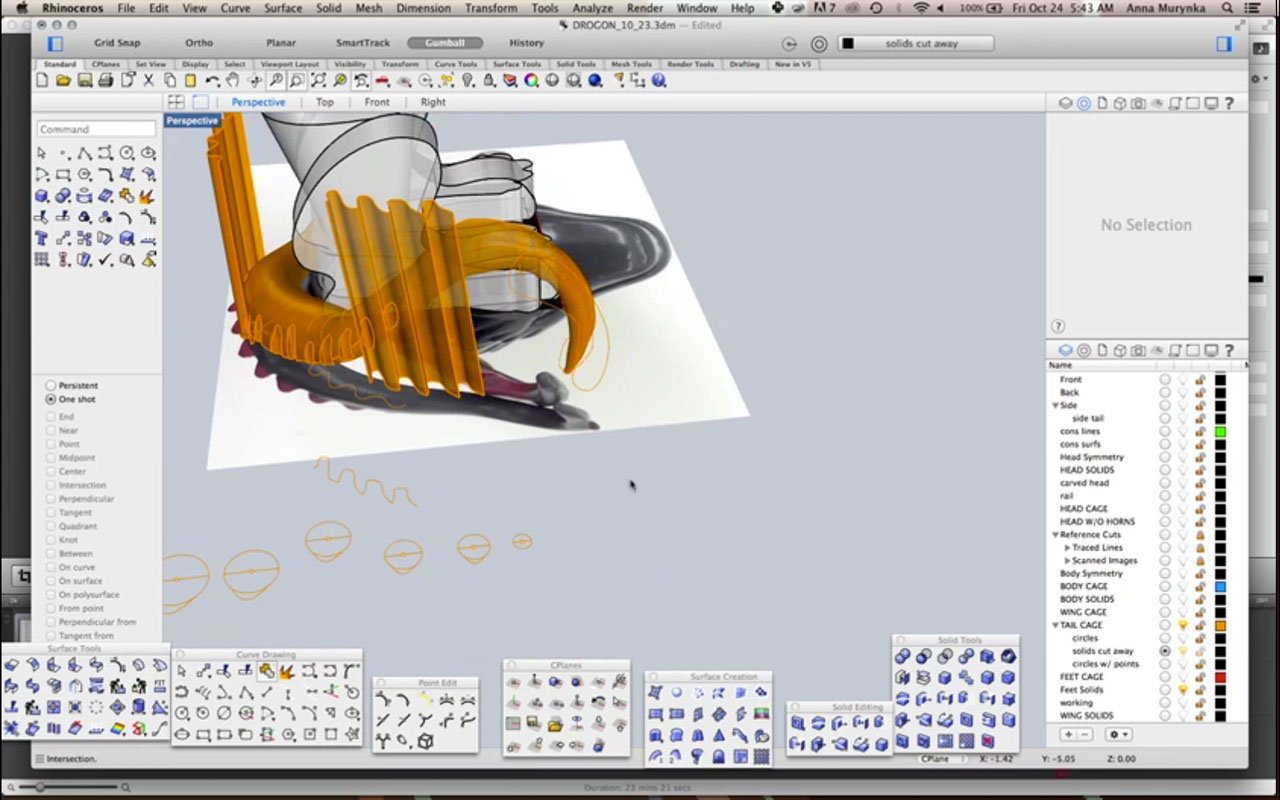
Connecting the various parts presented a bit of a challenge: the mouth in particular had too many disconnected edges, and I ended up having to revisit it and come up with other solutions. Once the entire toy was assembled (ears, head, mouth, nose, body), I began creating renderings in Keyshot. After playing around with different materials, I went back to the Rhino model to separate the model into layers according to colours. I then brought it back to Keyshot and used the plastic materials as colouring, as well as adding a backdrop image found at http://f.fwallpapers.com/images/nightmare-christmas.png.

zero-appropriate-colours


Zero-rendering-with-background

Zero-Floating!


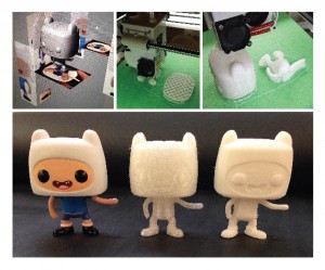
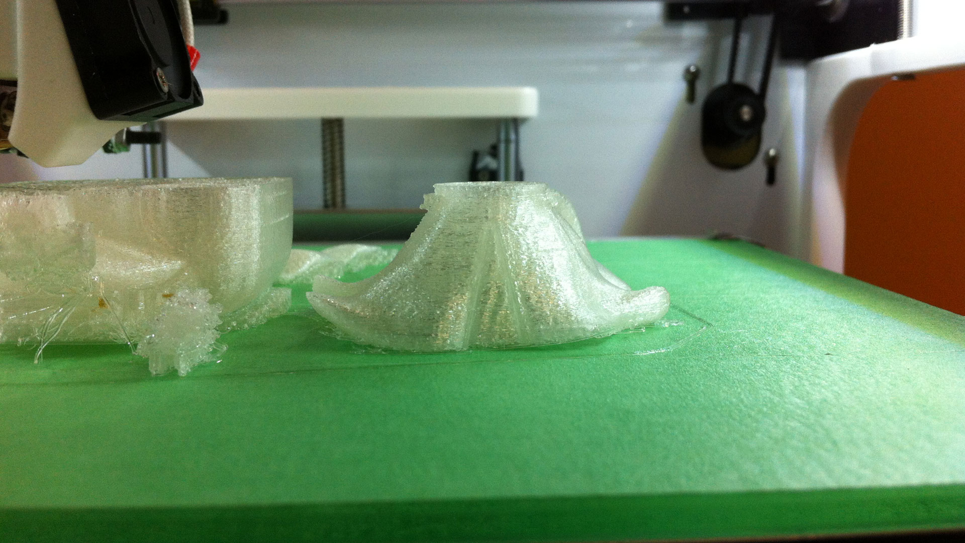
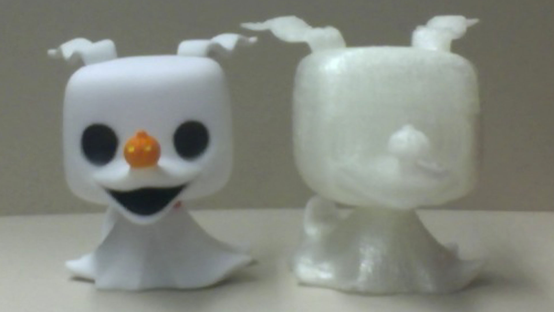
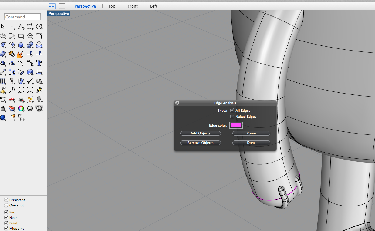
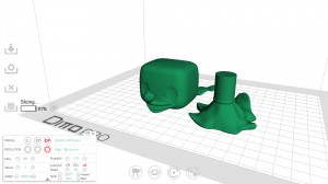
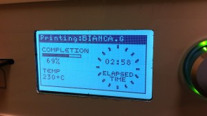
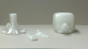
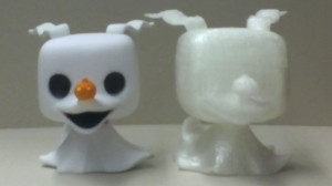
The next part was the actual 3D printing: I quickly discovered there were a few more steps before bringing my Rhino model into Tinkerine, such as getting rid of naked edges, creating meshes, and exporting each piece into an stl file. I decided to print the body, head, and ears separately in an attempt to use less support material to speed up the process, and also to allow the head to be able to turn. A problem that came up while printing was that the PLA material did not stick to the base surface very well, so the bottom surfaces ended up with gaps where the material was pulled away by the printer head. Overall, the 3D print result worked, although with less detailed precision than I had prepared for.

Zero-Slicing-in-Tinkerine3D-printing-part-way print-timeseparate-parts-3dcomparison

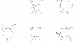
To finish up the project, I used the Make2D command in Rhino to generate line drawings of the figure from different views. To improve the drawings, I then added and deleted specific lines.

zero-line-drawing


Final-Rhino-Mess


Finn the Human: Let’s Try This Again (Attempt #3)

After organizing all my layers so neatly and tracing all the slices (top and bottom) I still can’t quite get these surfaces to come together the way I want them to… I have decided to finally abandon these beautifully organized layers and follow the route most others have discovered – tracing images of the original toy.

During this step you have to be very careful to take pictures with the least amount of distortion as possible – impossible to take a photo without at least a small amount of perspectival distortion so try focus only on the nearest parts of the toy when tracing.

Screen Shot 2014-11-15 at 4.45.58 PMphotos

**Later I moved these images with their tracing together to meet in the middle**

WEEK 6 Progress

Leanne- Cake is almost done being modelled minus some work that needs to be done on details and creating closed surfaces. In our last post we were experimenting with creating the shape of the body and in this post I will show how I created the extremities and details (mostly commands such as surface network, ellipsoid by diameter, sphere by diameter, sweep2, boolean union, split, join, and by manipulating control points on objects).


First image

Above is the nearly finished version of Cake.


2nd Image

I started with the arms and eyes. The eyes were simply made with the command “elipsoid by diameter.” I took measurements directly off of the doll and made the elipsoids to this dimension. The arms were made by tracing a photo of the front view of Cake. I traced the arms and compared this with measurements directly from the model. I placed an elipse at the bottom of these two lines and did the Sweep 2 command. I then capped the holes to have closed objects.


3rd Image

Next I attempted the feet. I struggled with this a little bit. First I attempted a method using thenetworksrfc command (the brighter red foot on the right). I traced the shape of the bottomof the shoe off of the model, then created a wire frame of the shoe based off of photos and measurements. It was really hard to accurately measure and I realized I was getting too detailed. I was getting tired and the foot came out really terribly. I decided to try a new method. This was to manipulate control points on an ellipsoid. I manipulated them to match up with the actual footprint of cake and the outcome was much better than the first. I trimmed the new shoe with a plane (as you can see in the photo) and then capped the object.


4th Image

Finally I worked on the nose. It took a few tries to get it right. The first attempt was to manipulate control points on a sphere. The second was to take the profile, use photos and measurements and create a wireframe to run the networksrf command with. This did not work for me. It was too finicky and a waste of time. I ended up going back to manipulating surface points to get a desirable outcome. I did the same with the tip of the nose and have yet to figure out how to join these to objects.


VIK 1

Viktoria – My approach was to combine tools like pipe, surface curve, patch, loft.  I ran into issues in making the fingers – I attempted to pipe separations and then split the difference then fillet to smooth them but the effect was not entirely successful in making the hands accurate to the actual object.  I also had to reconsider some approaches when I considered the rendering requires, so make separate pieces that would be the different colours of the model. To make the face I traced the eye in front view from the photo then extruded through the torso booleaning difference to create a circle that warped to the contours of the torso then making surface curves to create the shape.  I had initially attempted to create the eyes using spheres but found that method inaccurate and harder to control.  I will rework the facial details in my next iteration for further accuracy and fidelity.  This current model is not ready for 3d printing yet as it is not water tight – there are some ‘messy’ bits on the inside that need to be cleaned up and edges that need to be closed.

VIK 2 VIK 3 VIK 4 VIK 5 VIK 6 VIK 7 VIK 8 VIK 9 VIK 10 VIK 11

In playing around with my renderings I had a few different approaches – I used matte paint materials for one model and metal paint materials for another.  The matte version (though more like the actual model) came out looking dull in the render.  The shinier metal paints gave the rendered model more dimensionality and liveliness but is less true to the actual model.  I also realized in rendering that I am missing an orange arm patch on one arm, and that the back of the mouth/throat needs to be separated in my Rhino model so that I can colour it separately

lVIKTORIA RENDER 1VIKTORIA RENDER 2 VIKTORIA RENDER 3 VIKTORIA RENDER 4

zero vinyl toy head

zero-oct-25

After Kara scanned our cuts of the toy, we brought them into Rhino (with the PictureFrame command) to trace for further accuracy. I had traced the head from photographs and used RailRevolve to form the basic shape of the head. I also used RailRevolve for the pumpkin nose. I formed the eyes by making ellipse shapes, measuring where they were supposed to be on the head, and using BooleanDifference.

ear-progress-25

curved-ears

One of the most difficult parts to figure out so far have been the ears. I began by tracing a Top View of the ears with a ControlPointCurve, then moving into Right View to manipulate the straight curve into an undulating shape. The most successful smooth edged ear so far ended up coming from the Sweep2 command.

Zero’s mouth is even more of a challenge : some failed attempts used the commands RailRevolve, EdgeSrf, Extrude along Crv… The mouth that worked the best was made using a lot of curves traced from the photographs and scans and the Sweep2 command. There is still an unwanted ridge in the middle, but is the most successful attempt so far.

zero-mouth-fails

a-better-mouth-oct-25

My next steps will be to refine the head, and work on the body.

oct-25-curved-ears


DROGON PART II

Liyang and I, having scanned and scaled and the physical section cuts, then went about importing them into 3D modeling space. Andy gave us the great tip that the saw mill cuts out ~2mm, so we used this in addition to our measurements to arrange the cut reference files.

g_modeling

We were careful to be neat with our layers, labeling, and organization.

1

We then began to tackle the body in parts. For example, with the head, we found a plane of symmetry, mirrored the reference lines, and began to form a network of curves.

2

The next step is to work with solids; we experimented with different ways of forming solids and booleaning them.

3

We found that our section cut references were not informative enough on their own, so we supplemented them with imported elevations. We also frequently referred to the physical toy, feeling it and examining it.

4

Other parts of the figure included the torso, feet/legs, wings, and tail.

5

Some methods yielded convoluted results. This is definitely a process of trial and error.

6

Many techniques used in combination lead to the best accuracy and intricacy.

7

Here’s the screenshot of the current state of the model. Not there yet, but well on the way:

8

Modelling toy super hero

The initial steps involved spray foaming the toy and cutting it into sections. Cut lines were chosen based on what curves we thought would be  most important when 3D modelling. Once the cuts were brought in to Rhino, they were scaled and traced to create construction curves. Reference photos of the complete toy were then imported, scaled and arranged in space. The next step is to align the traced curves behind the reference photos and build a framework we can build from using curve network etc.

importing cut sections and tracing outlines
Tracing cuts with curves
inserting and scaling reference photos