In 2024, we hosted two two-week workshops. One was for ~50 students in grades 5-7, and the other for ~50 students in grades 7-9. Here we include example lesson plans for both sessions, as well as age appropriate slides.
Materials / Space Requirements
- Large well ventilated room with long worktables
- Around 6 supervised soldering stations with:
- Fan or ventilation
- Soldering iron
- Solder
- Desoldering Iron
- Third hand
- Wire cutters
- One adult instructor
- Screwdrivers: We distributed screwdrivers from a number of different kits (around 15 different sized kits of screwdrivers) at the front, depending on what students needed. We found its important to have as much variety as possible, including many different tips, and long-handled screwdrivers.
- Devices to disassemble / repair: We had around 10 toasters and ten hairdriers. These can be found for ~5 each at thrift stores, or at the recycling depot. We also asked students to bring in their own broken devices if possible.
- Cleaning materials: Some fans were dusty etc. We had damp cloths, wet wipes, and hand sanitizer on hand
- Safety equipment: First aid kits, fire extinguisher etc.
- Snacks
Electronic Design and Repair Workshop: Session 1 Outline
Slides: Repair Workshop Week 1 (Grades 9-12) Repair Workshop Week 1 (Grades 9-12).pptx
9:00 – General Introductions:
Lets start with a quick introduction to the workshop, what everyone can expect and what our goals are.
- Introduce the instructors
- Go over the plans for the workshop
- Brief motivation for the workshop (an introduction to electrical and computer engineering, hands-on experience with electronic repair, and a discussion of how engineering can relate to sustainability and waste)
- Ask students why they are there and what they would like to learn
- Activity: Give tables/groups a chance to introduce themselves to each other and come up with a team name.
9:15 – Introduction to safety and equipment:
We’ll go over basic safety when working with electronics. We’ll avoid ever having to plug in the devices without close supervision, but can still talk about dangers of electronic repair and how they can be mitigated. We can also go over the equipment at their stations.
- Avoiding electric shocks: The difference between AC/DC power, identifying and being careful with capacitors, avoiding plugging anything in etc.
- Safe soldering: What is soldering and how can it be dangerous? Discuss fumes, burns and ventilation
- General safety: keeping a clear workstation, tying back hair, being careful during disassembly
and asking for help when required. - Activity (for younger age-group): Spot the safety-related problems in a picture of students
working at a lab station.
9:30 – Introduction to Ewaste – Motivating Repair
Why is repair important? We can start with a discussion of ewaste, and how it is harmful to the environment.
- Ewaste: How much ewaste is there? Where is it sent? What are the environmental and social dangers associated with electronic recycling and disposal.
- Embodied carbon: Discuss the carbon produced during the production / recycling of electronics,
compared with operational carbon. Life cycle analysis - Solutions: Why repair is important, but why it is difficult. Planned obsolescence.
- Activity: Think back to the last time they threw out an appliance or device. Why? Why was repair hard? What could have been done to deal with the situation more sustainably?
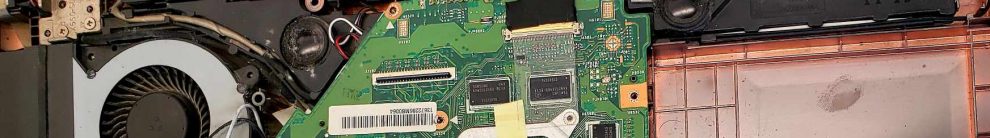
9:45 – Disassembly of a device
Lets have them disassemble their group’s device early on so they have a real life circuit to look at during discussions of circuit components, circuit diagrams. We can provide each group with either a toaster or hairdryer
- Activity: Take apart their group’s device. Doing this carefully can take some time.
- Discussion of how this went. Was it easy? What made it hard/easy?
10:00 – Circuit Components
Now that they have a real-life circuit in front of them, we can go through different electrical components, what they are used for, what they typically look like and how to identify them.
-
- Resistors
- Capacitors
- Integrated circuits and chips
- Motors
- Switches
- Activity: Identify the main components on their disassembled circuit and draw them / describe them on a worksheet.
10:15 – Drawing a Circuit Diagram
To understand how a circuit works, we need to look at how the components are connected and how electricity flows between them. A clear way to do this is to make a circuit diagram that maps out the electrical components and how they are connected.
- What is a circuit diagram?
- How does electricity pass through a circuit? (things connected in parallel versus in sequence)
- Activity: Draw a circuit diagram of their circuit and how the components are connected.
10:30 – Break
15 minute break
10:45 – Voltage, Current, Resistance
The younger and older age groups might have different amounts of experience and different ability levels here. In both cases though, we can give a brief review / introduction / overview of the ideas of resistance, current, voltage and power through the analogy of pipes and water
- Current – the amount of water passing through a pipe
- Voltage – water pressure
- Resistance – pipe size
- Short circuits and open circuits – blocked pipes and leaks
- Basic circuit equations (for older students)
- Activity (for older students): Solve for voltage / current / resistance in a few simple example circuits.
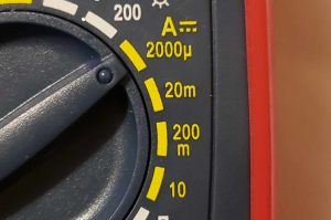
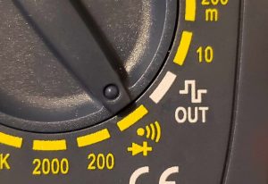
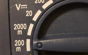
11:00 – Using a Multimeter
Analyzing, debugging and repairing a circuit typically involves using a multimeter. We can go through and practice a few different types of measurements done using multimeters.
- Testing connectivity
- Measuring resistance
- Measuring capacitance
- Activity: Measure the resistance of a resistor, and investigate the switches in their circuit. Label measured values (resistance, capacitance etc) on the circuit diagram.
11:15 – Electronic failure and repair
Now that we understand a working circuit, what could cause this circuit to break?
- Discuss common causes of failure: burnt out / disconnected wires, damaged components, blown
fuses - Brainstorm how this could happen for their devices, and other possible causes for failure –
crumbs stuck in the toaster electromagnet, fuses from hot hairdryers. - Activity: Given a scenario where, for example, the toaster lever doesn’t stay down. As a group we can go through the process of debugging this. Eg. When the lever is pressed down, does the toaster get hot? Check the connectivity of all the components? Does the switch still work? Are there crumbs in the electromagnet?
11:30 – Designing for robustness and repairability
We can wrap up things by talking about how to design electronics that are better – that are easier to repair and that are less likely to break.
- Design practices for robustness and design tradeoffs
- Design practices for repairability and design tradeoffs
- Activity: In groups, come up with an improvement to your device, and present the new and improved device.
11:50 – Conclusions
We’ll finish up by reviewing what we went over during the workshop, talking about what to expect in the next workshop, and asking for feedback and questions.
- Review of what we did and learned
- Explaining the plans for the next lesson and what to expect and bring
- Question time
Electronic Design and Repair Workshop: Session 2 Outline
Slides: Repair Workshop Week 2 (Grades 9-12) Repair Workshop Week 2 (Grades 9-12).pptx
9:00 – General Introductions:
Lets start with a quick introduction to the workshop, what everyone can expect and what our goals are.
- Introduce the instructors
- Go over the plans for the workshop
- Review the motivation for the workshop and what topics we covered during Session 1.
- Activity: Give tables/groups a chance to introduce themselves to each other (likely the groups
will be different)
9:15 – Review of safety and equipment:
We talked about this during the first session, but its important, so lets review it again.
- What safety issues and precautions do they remember from the last week? What have they forgotten?
- Activity (for younger age-group): Spot the safety-related problems in a picture of students working at a lab station.
9:30 – The repair process – how to approach a repair.
We will have them bring broken devices from home. They can choose one to try and repair. We can first go through the basic steps of repair though:
- Approaching a repair: What works/ doesn’t work? When did it stop working?
- Activity: Take a look at the device they brought. What works and what doesn’t? What is the history of the problem?
9:45 – The repair process – Disassembly of the device
Lets have them disassemble their group’s device early on so they have a real life circuit to look at during discussions of circuit components, circuit diagrams.
- Activity: Take apart their group’s device. Doing this carefully can take some time.
- Discussion of how this went. Was it easy? What made it hard/easy?
10:00 – The repair process – understanding the circuit
Now that they have a real-life circuit in front of them, we can review different electrical components, and drawing a circuit diagram.
- Resistors, Capacitors, Integrated circuits and chips, Motors, Switches
- Activity: Identify the main components on their disassembled circuit and draw a circuit diagram
to the best of their ability.
10:30 – Break
15 minute break
10:45 – The repair process – what could have broken?
Its not always easy to figure out, or visible what the problem with a circuit is, but there are some common problems that we can go over to start with.
- Common problems and why they happen: Blown fuses, burnt out capacitors, resistors,
disconnected wires. - Review how to use a multimeter to check connectivity, resistance etc.
- Activity: Take a look at the circuit and look for obvious problems, like disconnected wires. Try to go through each component checking that it is connected and working.
11:15 – The repair process – fixing a problem
Hopefully we found the problem in the circuit. Here we can talk about how to fix basic problems, and what to do if that isn’t possible.
- Soldering – how to fix disconnected wires and replace components
- Finding and ordering new parts. Discuss right to repair legislation.
- Activity: Can the circuit be repaired? We can have soldering stations set up to repair things where possible.
11:30 – Presenting to the group
Every repair is different, and the same thing (eg. A toaster) can be designed in many different ways. We can have each group briefly present their device, the process they used to disassemble and attempt to repair it, and how it could be improved to make it more repairable or durable.
- Activity: In groups, with flip-charts, prepare a brief presentation of the broken device, the
circuit diagram, what broke (or a guess as to what broke), how it could be fixed, and what could
be done by designers to prevent or improve the problem.
11:50 – Conclusions
We’ll finish up by reviewing what we went over during the workshop and asking for feedback and questions
- Review of what we did and learned
- Question time