The original arm design featured a lasso design. Airplane cable would warp around the passenger, and the cable would be tightened and loosened via an encased spool. This design ultimately proved impossible due to motor strength constraints.
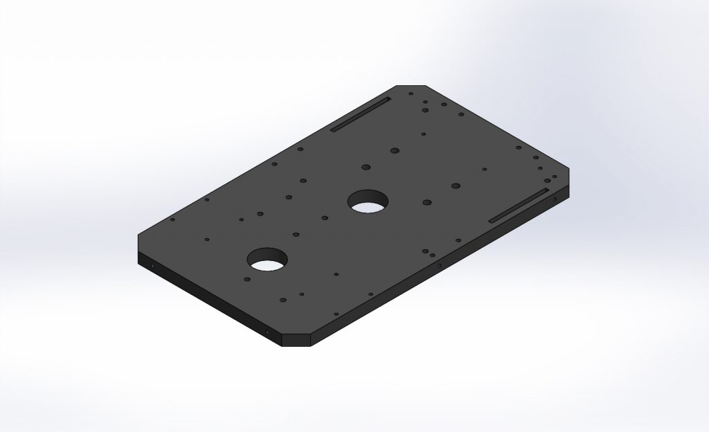
The final chassis design, waterjet cut out of 3/8” polycarbonate, features a 10”x6” outline. Numerous holes in the structure provided places to mount mechanical components and facilitate wiring.
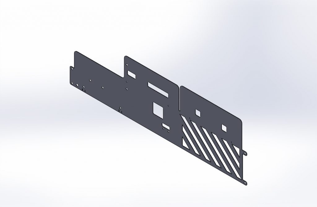
This part shows how sheet metal was used in the robot design. Used to encase the chassis and electronic components, our sheet aluminum painted casing provided a professional aesthetic to the robot and helpfully enclosed the inner electronic components.
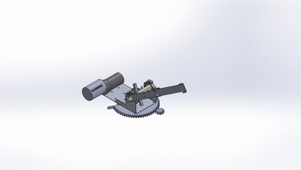
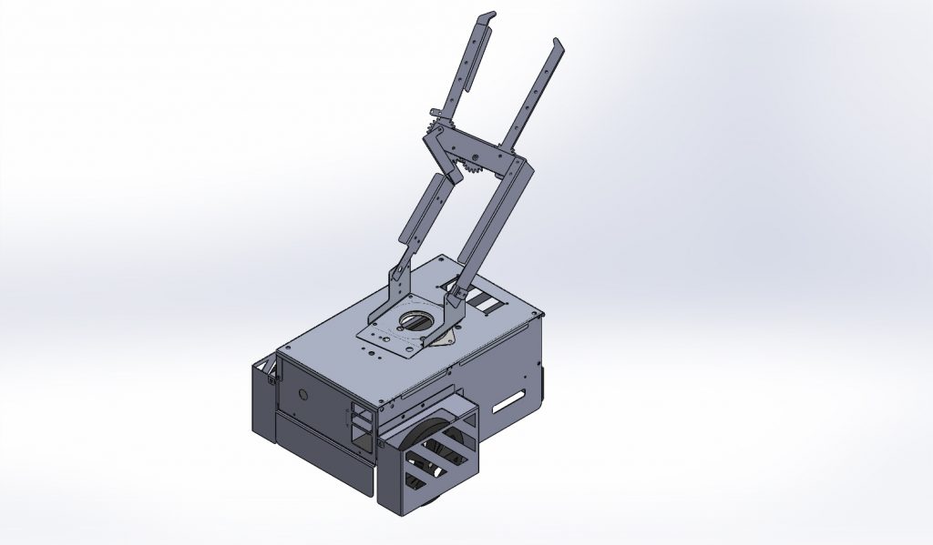
The final full assembly of our robot in SolidWorks. Assembly files were kept up to date during the design and construction process.
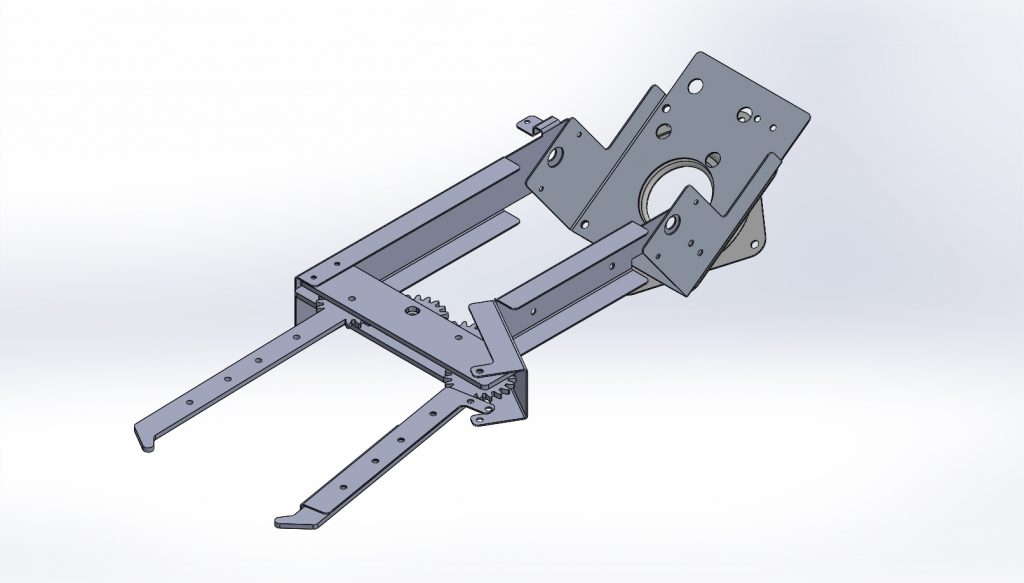
Our final claw was more simplistic and effective than the original lasso design, renewing our team’s focus on simple solutions to complex problems. The claw length allowed easy pickup of passengers at all legal competition distances.
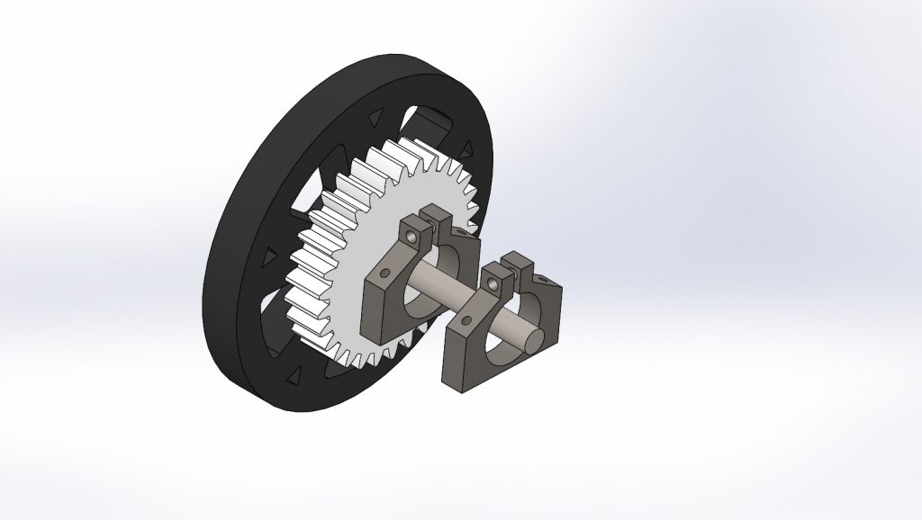
The final wheel assembly used a combination of bearings and polycarbonate clamps to firmly fix the wheels to the chassis. Our wheel attachment was extremely robust and performed very consistently throughout testing and competition.