ESSENTIAL TERMS AND CONCEPTS*
*Scroll to the end for discussion of the difference between common and technical definitions for axonometric and other parallel projection types.
Parallel projection
Parallel projections include all orthographic and oblique drawing types, sometimes collectively referred to as “paraline drawings”.
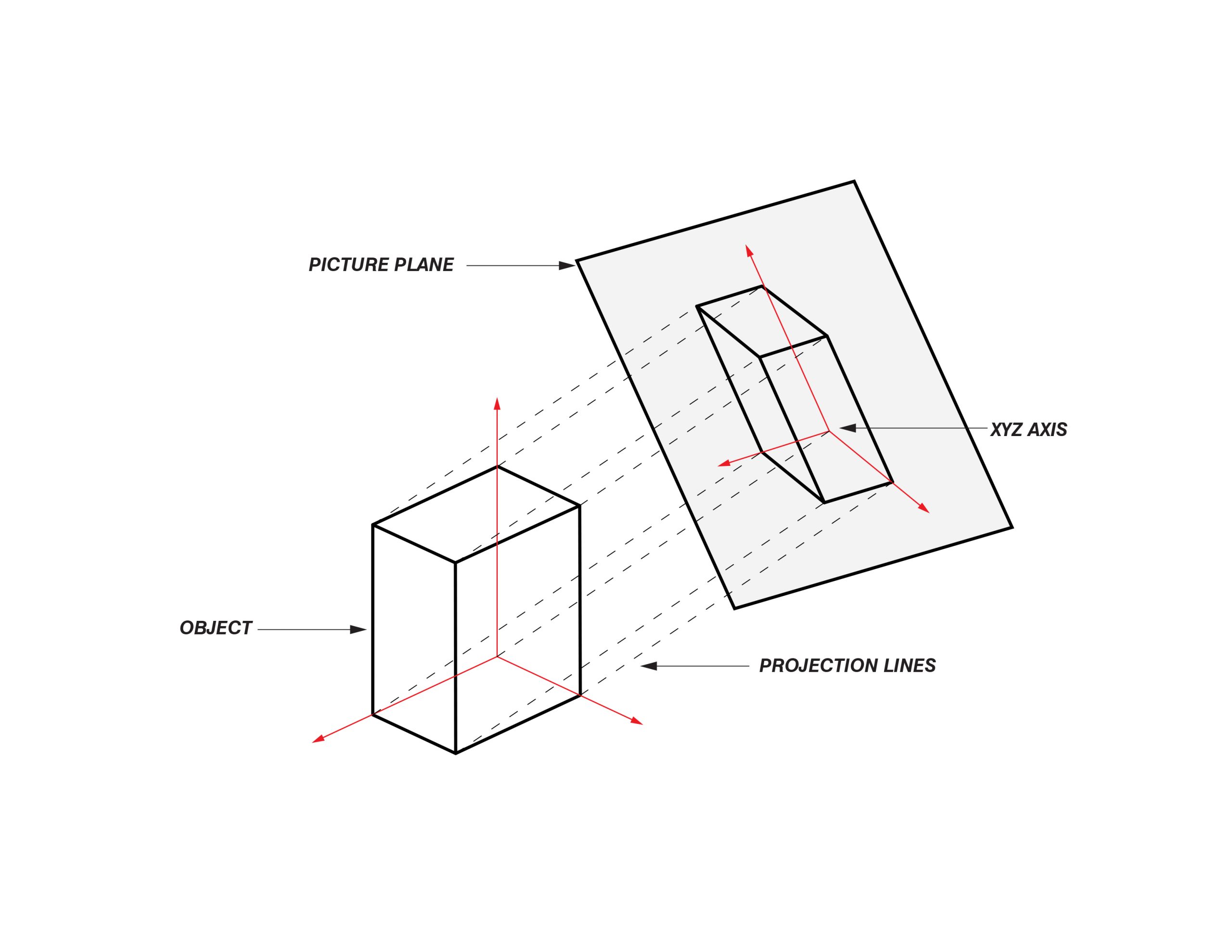
Any 2-D representation of a 3-D object, be it parallel projection or perspective drawing (collectively, graphical projection), involves the imaginary projection of points from the object to a single plane – a sheet of paper or a screen. Parallel projections assume an infinite distance between object and plane, such that parallel lines could be drawn between real points on the object and projected points on the plane. By shifting the angle and position of the plane and observer, we can create varied orthographic and oblique (non-orthographic) projections.
Different parallel projections are used to preserve or emphasize different spatial relationships. For example, an ‘axo’ (45-45 plan oblique) maintains a true plan in the horizontal plane, while an elevation oblique maintains a true elevation in one vertical plane. An isometric distorts all planes equally, providing equal emphasis but deviating from orthographic plan and elevation information. These drawing types are explained in more detail below.
AXONOMETRIC
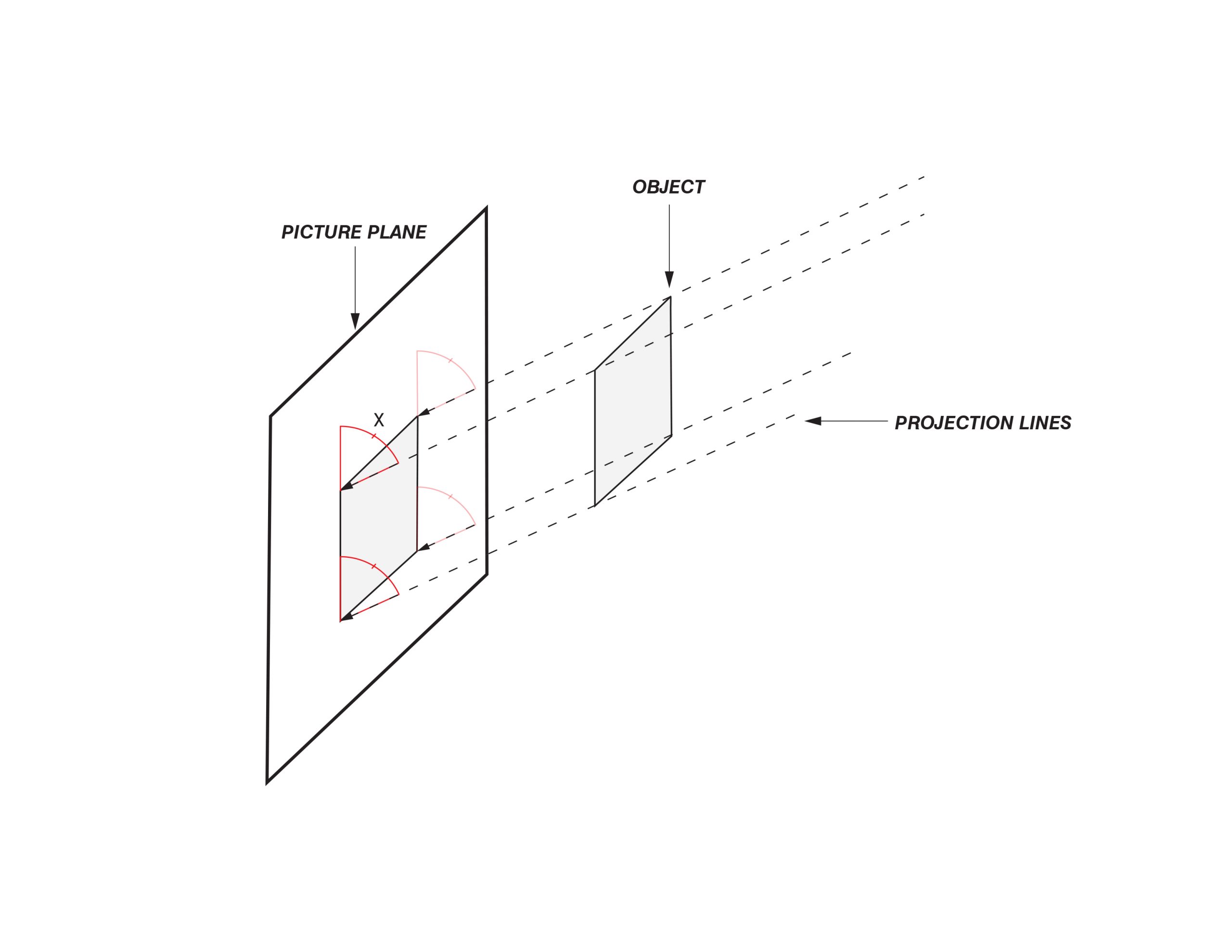
The axonometric drawing, commonly referred to as an ‘axo’, is an oblique projection with projection lines that arrive skewed relative to the picture plane. In an ‘axo’, the object is projected such that it sits in either a 30-60 or 45-45 degree pair relative to the 0 line – a line which provides reference to the picture plane. These concepts are illustrated in this glossary.
Axonometric drawings, also called plan obliques, are especially helpful to designers since they can be drafted quickly using an existing site plan – simply rotated to achieve the desired angle and representation.
They produce drawings that are visually distorted but provide an excellent tool for site immersion and visual recording which can assists designers in understanding a site and its context.
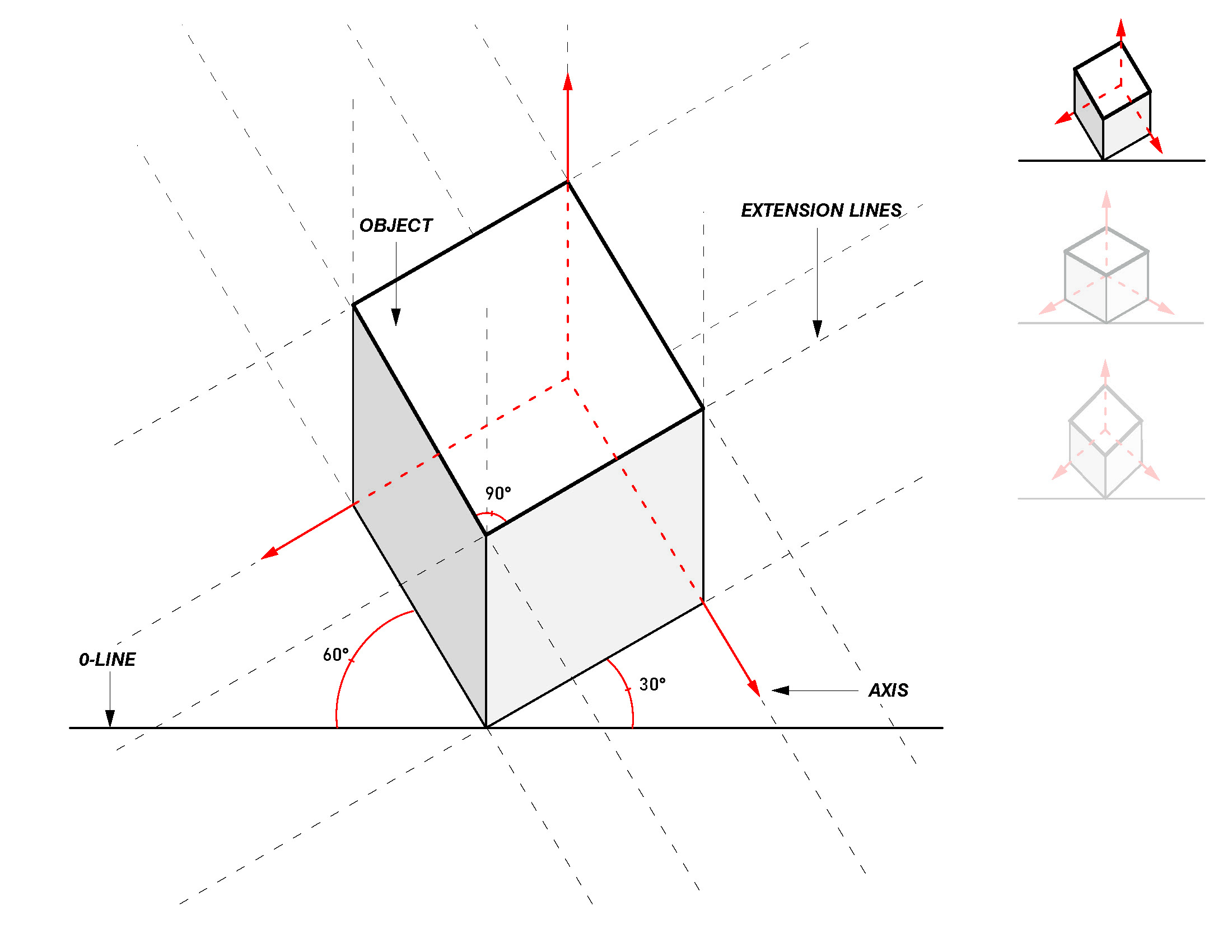
The 30-60° combination renders a projection that has one vertical face more visible than the other.
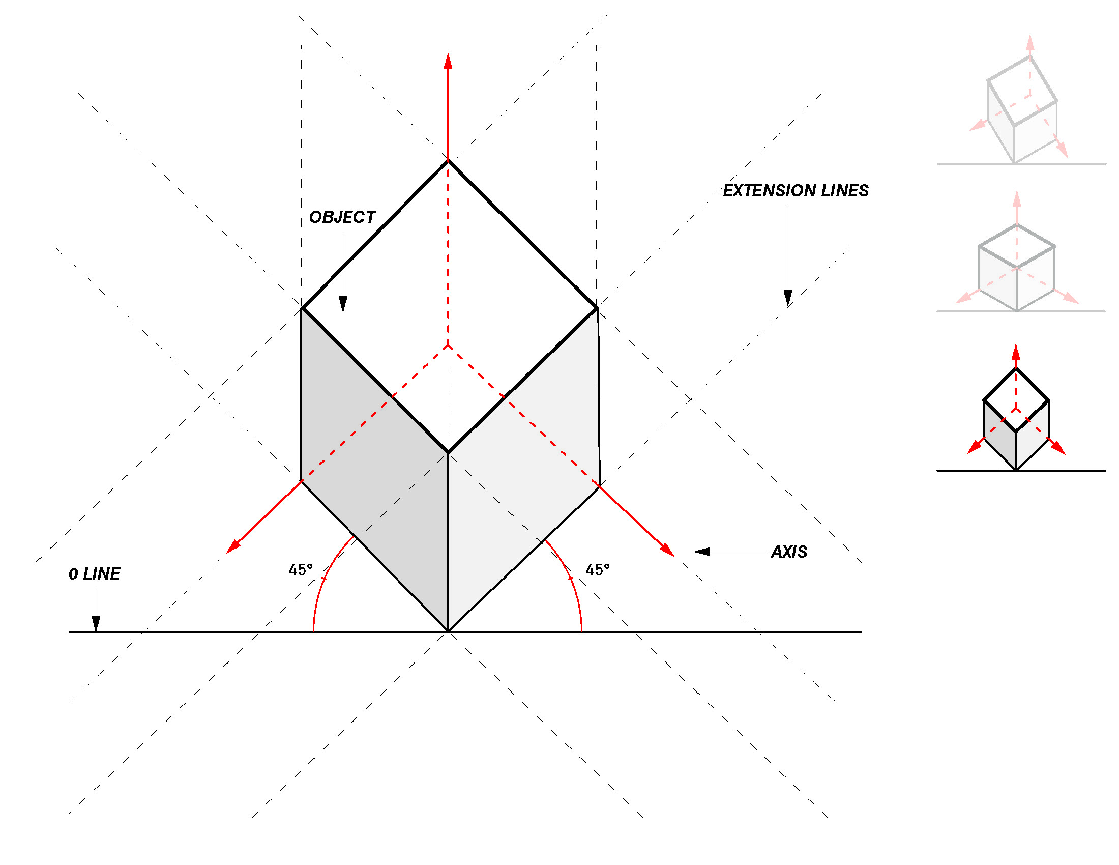
The 45-45° combination renders a projection that illustrates both vertical faces equally and thus emphasizes more of a horizontal view.
Military oblique
Though often referred to simply as an axonometric, ‘axo’, or plan oblique, military oblique is the technical term for the projection system used by the CUBE method. The military oblique is an oblique parallel projection that maintains an undistorted, or ‘true’, plan, angled 45 degrees from the 0 line.
Easy transitions between geometrically accurate plan drawing and spatialized site observations is what makes military obliques so useful for holistic site analysis.
ISOMETRIC
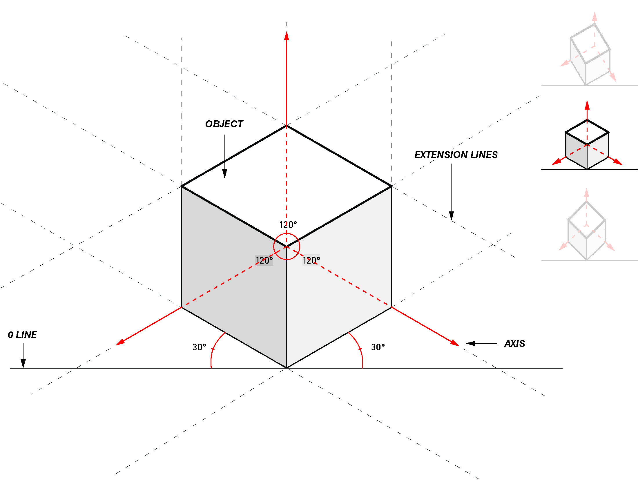
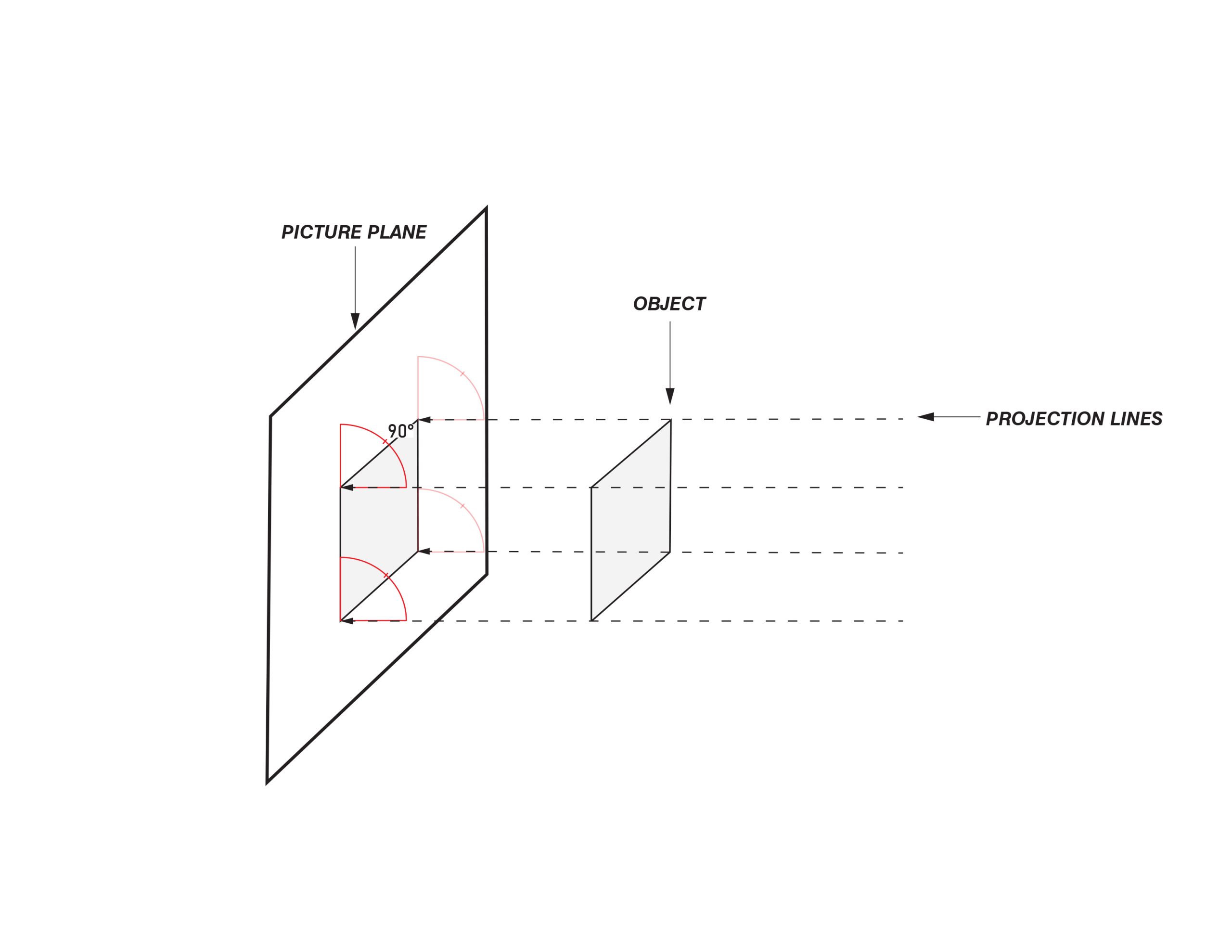
An isometric drawing, or ‘iso’, is a type of orthogonal projection with projection lines that are perpendicular to the picture plane. The term “isometric” comes from the Greek meaning for “equal measures”, wherein foreshortening occurs uniformly across the X, Y and Z-axis. The angle created between the 0 line and the projected object is the same on both visible sides – typically 30 degrees.
Other multi-view orthogonal projections are the diametric and trimetric which have 2 and 0 equal lengths of foreshortening, respectively.
Isometric drawings are an effective projection for diagrammatic and technical applications. They come from a distorted plan and therefore require to be drawn from scratch but produce drawings that are clear, measurable and less distorted.
ORTHOGRAPHIC PROJECTION
In orthographic projections – like the isometric – the projection lines from an object arrive perpendicular to the picture plane.
Other multi-view orthogonal projections include the diametric and trimetric. Single-view orthographic projections consist of plan, elevation and section.
adapted from: Perspektive und Axonometrie, Thomae, R. (2001)
oblique Projection
In oblique projections – like the axonometric – the projection lines from an object arrive at an angle to picture plane.
adapted from: Perspektive und Axonometrie, Thomae, R. (2001)
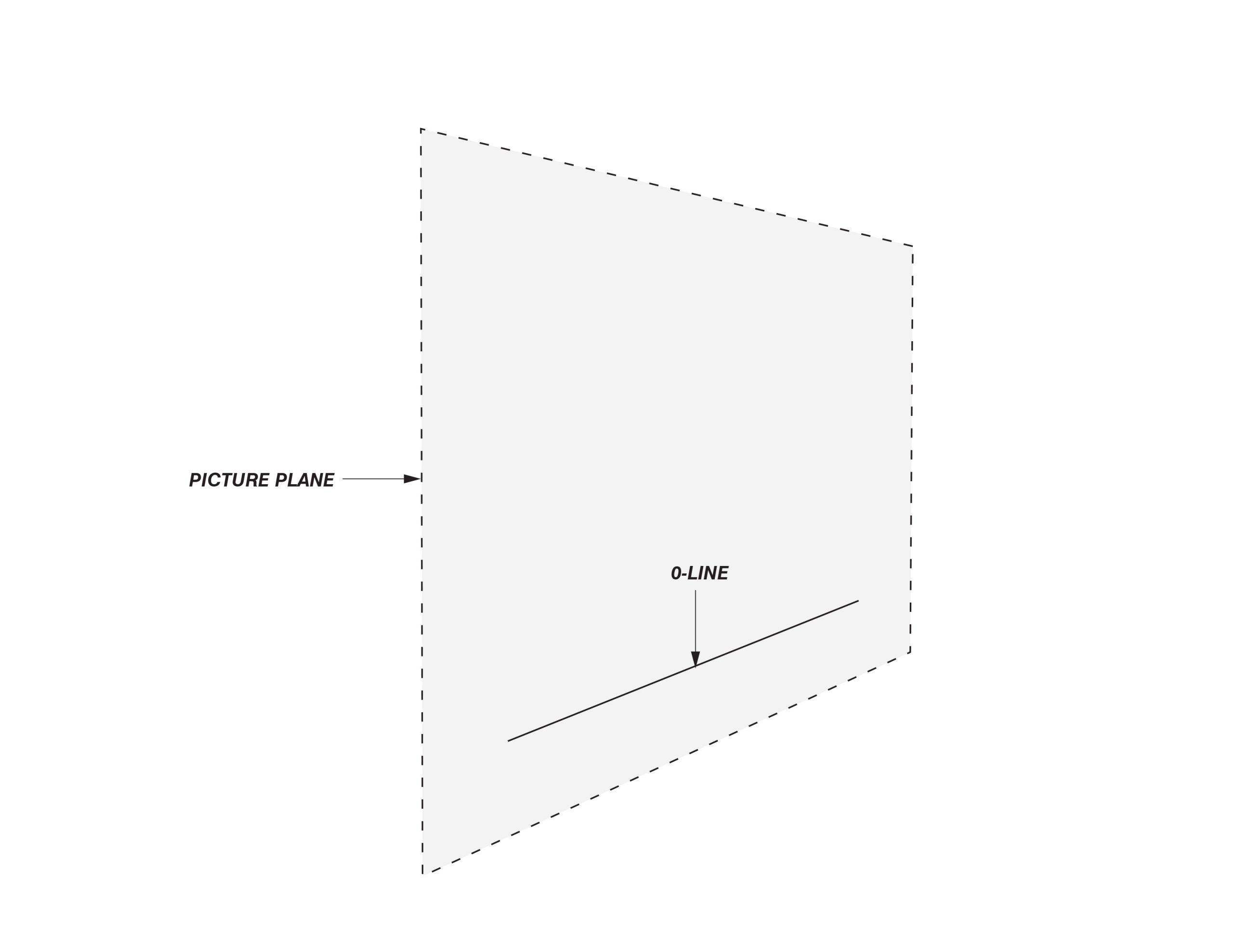
0 line
The 0 line is an imaginary reference line that is drawn parallel to the bottom edge of a picture plane. Projected objects can be understood and interpolated on the basis of their relationship to this line and, by extension, the picture plane.
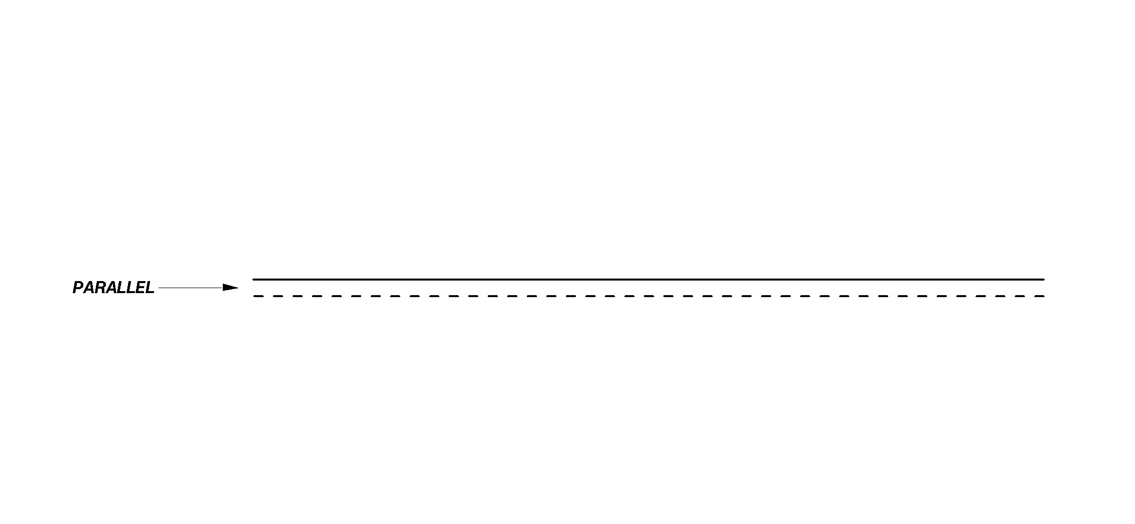
PARALLEL
Parallel lines are lines in 2-D or 3-D space that do not meet or intersect.
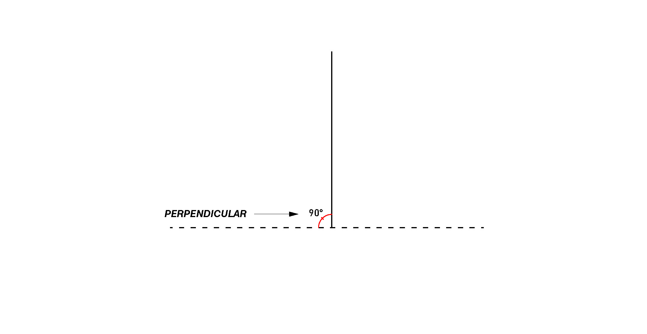
PERPENDICULAR
Perpendicular lines are lines in 2-D or 3-D space that intersect at a 90 degree angle.
PICTURE PLANE
A picture plane is an imaginary viewing plane upon which 3D objects are projected onto a 2D surface. Any 3D object represented on a 2D surface is being projected there via a picture plane.
adapted from: Raysper, Y. (2006)
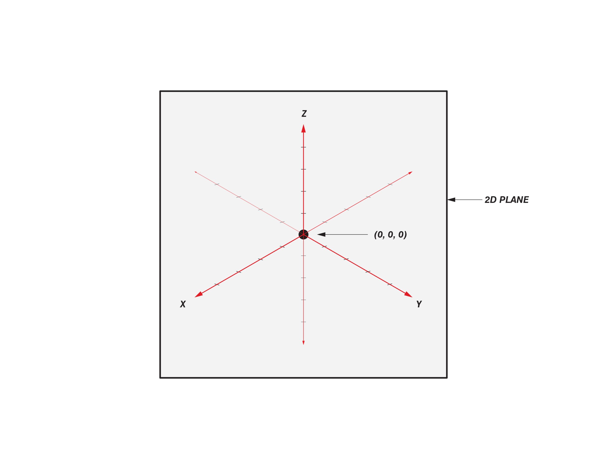
AXIS
An axis is a reference line drawn through or upon an object or a coordinate in either 2-D or 3-D space. Any given object can be understood through its axis. The X, Y and Z-axis and correspond to the three different directions in 3-D space.
When an object is projected from 3- to 2-D space, it is the distortion of its axis which expresses this ‘transformation’.
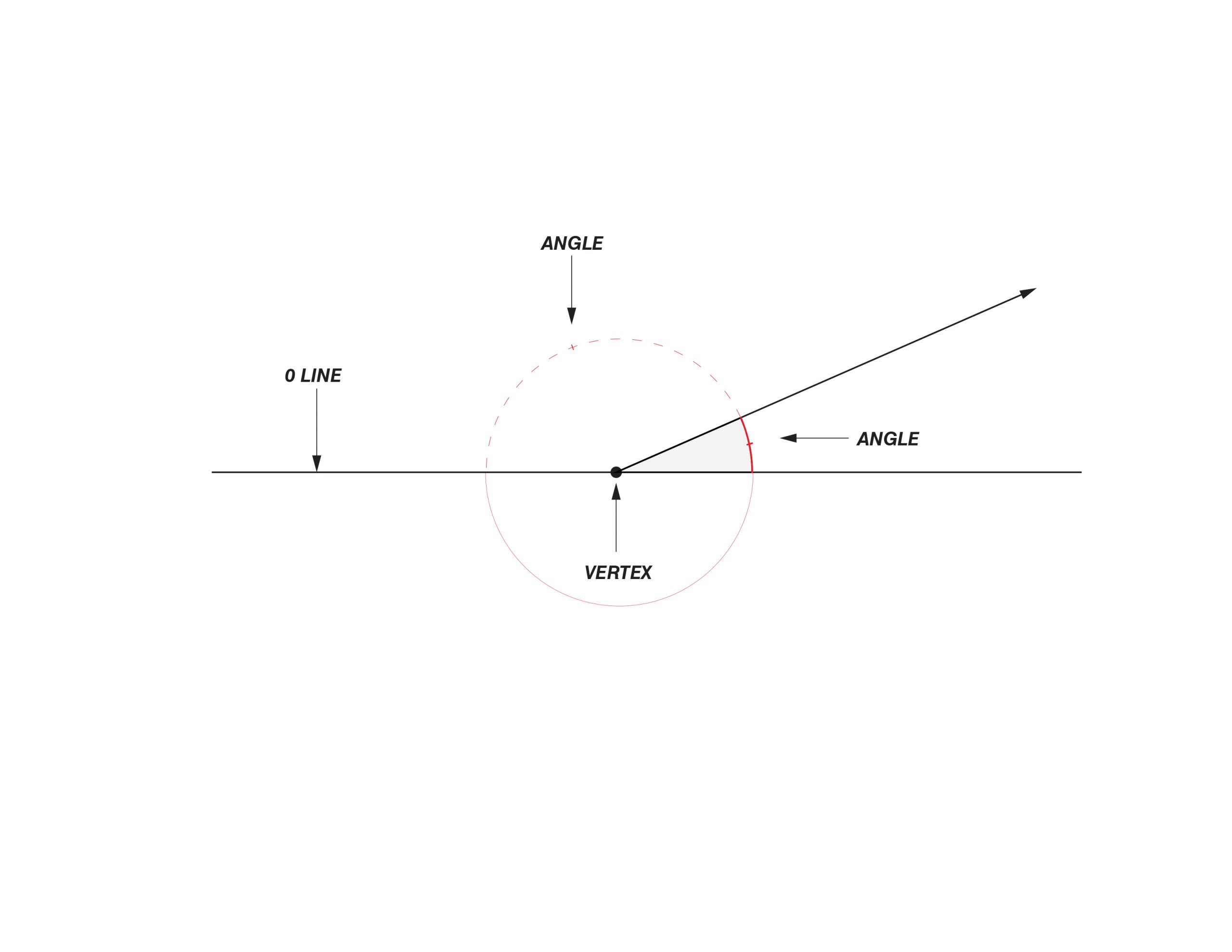
ANGLE
An angle is the measured relationship between two intersecting lines at their vertex.
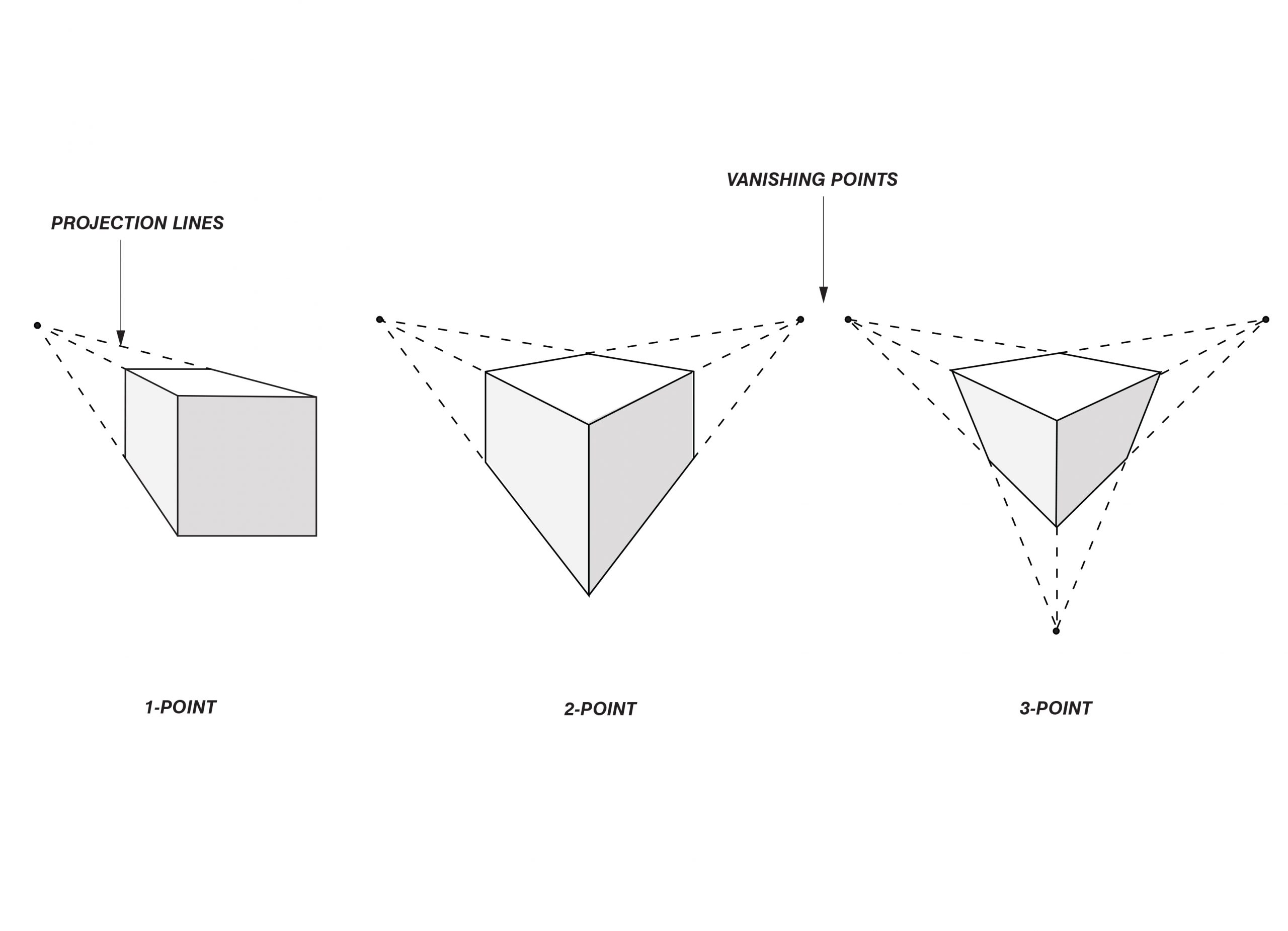
PERSPECTIVE
Perspective drawings are distinct from orthographic projections and use vanishing points to create an illusion of realism and are not parallel projections.
adapted from: cmglee (2021)
on terms and definitions…
As a method for measured 2-D representation of 3-D space, each parallel projection type carries its own strict mathematical definition, precise geometric relationships, and particular historical significance. However, in their common usage across design and engineering disciplines, the terms that refer to these methods can be relatively fluid. Specific and general concepts like axonometric (‘axo’), isonometric (‘iso’), plan oblique and orthographic projection are often used synonymously or as umbrella-terms, their definitions variously overlapping and contradictory. Though sometimes incorrect on a technical level, these flexible understandings work well for communicating within and across most design disciplines.
For example, in many professional and academic design circles, an ‘axo’ is commonly understood as a parallel projection that is true in plan and rotated 45 degrees from the 0 line. However, a technical definition of axonometric projection includes all orthographic views in which the principal axes are not perpendicular to the projection plane – isometric, dimetric, and trimetric views. Even then, this definition is somewhat contested. In German literature, axonometry refers to all types of parallel projection, including orthographic and oblique projection.
In this blog, the authors have adopted the terms and definitions commonly used in professional and academic discourse, which we believe are most useful given the intended use of the CUBE method as an approachable site analysis tool that can be readily adopted by students and professionals alike. Specifically, we use the term ‘axonometric’ and ‘axo’ to refer to a specific type of axonometric drawing, sometimes called a ‘military oblique’, that forms the basis of the CUBE method.
Additionally, and where relevant to the instructive purpose of the blog, we have included technical definitions and explanatory diagrams for different parallel projection methods. For further information, please see McGill University’s Engineering Design blog on Projection and Views (https://www.mcgill.ca/engineeringdesign/step-step-design-process/basics-graphics-communication/projections-and-views). Refer also to Architectural Graphics, 3rd ed. (Francis D.K. Ching).