Databases are built to support business information requirements. To design your database you need to understand the business data requirements. In this section we are going to look at modeling techniques to obtain conceptual, logic and physical data models which will help us to structure and implement a database.
Entity-Relationship Model
An entity-relationship model (E-RM) is a representation of the information classifications used to discuss initial requirements with the business stakeholders. It specifies the objects that need to be represented in the database in two categories: entities and relationships.
Entities
An entity is a real-world object distinguishable from other objects, generally expressed as nouns (“employee”, “customer”, “order”). It is described using a set of attributes which take a values from a given domain. Each entity has a key, an attribute (or a set of attributes) that uniquely distinguishes it from others.
Relationships
A relationship is an association among two or more entities, generally expressed as verbs (“performs”, “is assigned to”, “belongs to”). A relationship relating n entities will be an n-degree or n-ary relationship. As with entities, relationships can have their own descriptive attributes and keys that distinguish each one. These can be inherited keys from the entities they associate and they may also have their own key.

E-R Diagram example. Attributes can be drawn as ovals or listed inside the entity’s rectangle.
The cardinality of a relationship determines the number of relationships that an entity can participate in.
- one-to-one (1 : 1)
- one-to-many (1 : n)
- many-to-many (n : m)
Database Design Choices
There are often many ways to model a given scenario and design choices have to be made: should data be modeled as an entity or an attribute? should data be modeled as an entity or a relationship? binary or ternary relationships? The best choice is often subjective and depends on the meaning of the data and how you want to use it.
You can find other references for Entity-Relationship model in this Wikipedia article: Entity-Relationship Model. Here is another useful reference: ERP Theory.
Relational Model (RM)
While an E-R diagram displays the logical nature of the data that exists in the user’s domain, the relational model shows how this data will be represented in the Database Management System.
Transforming Entities
- Each entity is transformed into a relation, represented as a two dimension table.
- Entity individuals or instances are called tuples, which correspond to table rows.
- Attributes correspond to table columns.
Transforming Relationships
- 1 : 1 relationships: one of the two relations contains the primary key attribute of the associated entity table as a foreign key (indicated by an FK).
- 1 : n relationships: group together the entity and relationship tables that have a one-to-one cardinality. The primary key of second entity in the relationship becomes a foreign key in the absorbing table.
- n : n relationships: create a new table with the primary key attributes of both entities as a combined primary key
By the end of this process your database is organized in terms of the relational model, so it’s called a relational database.
Database Normalization
The process of organizing the fields and tables of a relational database to minimize redundancy and dependency is called database normalization. This is achieved by dividing large tables into smaller and less redundant tables, and defining relationships between them.
There is a trade-off between reducing your database redundancy and minimizing your query time, so fully-normalized databases are not always optimal. Introducing some redundancy in your database can simplify your queries and increase your database performance.
You can find more information and other references about relational model in this Wikipedia article: Relational Model.
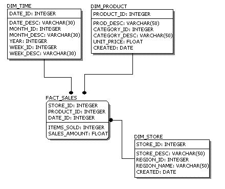
Physical Database Model
The final stage in the DB design is the physical database model. A physical DB model shows all table structures, including column name, column data type, column constraints, primary key, foreign key, and relationships between tables.
Physical data models can differ significantly depending on performance requirements or technology constraints. For example, de-normalization may occur based on user requirements, or a data type for a column may be different between MySQL and SQL Server. The DBMS selection is a decision that must be made at this stage.
If you want to learn more about data modeling, this Wikipedia article provides an overview and provides other references: Data Modeling.