
CNC
*The CNC is only available after approving the file with Graham, and cannot be booked online. Once the file is approved, email him directly to set up a timeslot. Each student is only permitted 4 hours per week, and must have completed Design Media II or had the course waived.*
![]()
Location
Please review the facilities page for CNC location.
Booking
You can book the CNC router through the online booking system. Jobs typically take one to four hours. Please meet with Graham, the CNC tech, as early as possible to show your file and discuss the best strategy for milling your job.
To book a CNC appointment, email Graham directly: gentwistle@sala.ubc.ca
Fee
Fees for CNC time are $11/hour with a $5 minimum charge. This includes file processing time.
Materials
You must provide your own materials. Generally they are wood products. Light weight MDF is the most common material used. The maximum horizontal dimensions are 45" x 80" (1,143mm x 2,032mm). Sizes of up to 48" x 96" can be cut by prior arrangement. The maximum thickness is around 10" (254mm). The maximum thickness for 2D cuts is about 3" (75mm).
For a full list of items available for purchase in the shop, please visit our materials page.
File setup
The CNC machine operates out of Rhino, and the breadth of possible work is diverse. Please discuss your project with Graham if you have questions.
For all files:
- Create a new file for digital output. You can easily do this by saving your file under a new name.
- Delete everything that isn’t required.
- Remove layers that aren’t required.
- Explode all blocks and remove the definitions.
- AutoCAD: Use Overkill to get rid of unnecessary lines.
- AutoCAD or Rhino: Use the Purge command to get rid of unused blocks and layers.
- Ungroup everything.
- Change the units to inches.
- Scale the model to the correct output size.
- Remember to meet with staff to discuss your job.
2D Setup:
- Use only polylines and splines. No surfaces for 2D cuts.
- Make sure everything is at z = 0.
- Create a rectangle the size of the material you are going to cut. The material sold in the shop is either 24" x 32" or 30" x 30". Position the rectangle so that one corner is at 0,0. Align the model so that the longer side is along the x axis.
- Arrange your parts inside the rectangle such that there is a 1" border around the outside and at least 3/4" between parts. This is necessary to maintain the integrity of the material during milling.
- Ensure that all part outlines are closed. That means that the end of the outline is at the same point as the beginning with no gaps or overlaps. *If you use VectorWorks, make sure that Grid Snap isn’t overriding object snap. Turn Grid Snap off to be sure you are really snapping to the beginning of your line when you close it.
- Make sure that there are no lines buried under other lines. This will confuse the toolpath program.
- If there are places where you want to cut on the inside of a closed curve, put these on a separate layer than the cuts on the outside of such a curve. If there are lines that will be etched into the surface, put these on a separate layer.
- Create a separate file for each panel that will be cut.
3D Setup:
- The material to be cut will be rectangular when looking down in Top view. The entire area of the rectangular material must be covered with a surface when viewed from above. The cutter will plunge through any gaps.
- Delete objects that are inside or beneath other objects.
- Trim any objects that extend past the footprint of the material.
- In Rhino, use the command BoundingBox, select all, and press enter twice. This will create the smallest possible box around your entire model. Select All again and move and/or rotate the whole works so that a top corner is at 0,0 and the model is in the +x,+y quadrant. Delete the bounding box. Align the model so that the longer side is along the x axis. Now your model will be in the correct position for milling.
- The deeper a bit has to cut (i.e. the greater its length), the greater its diameter will be. Instances with large vertical drops (whether 2D or 3D) will require larger diameter bits and will give less resolution. Therefore you will get better resolution with thinner materials if you are making 2D cuts or by eliminating tall buildings if you are doing 3D cuts.
- If you are milling a site that has large buildings, you can just create a flat footprint and make the building in the workshop and glue it on. This will speed up the job, save material and allow smaller bits to be used for the finishing pass.
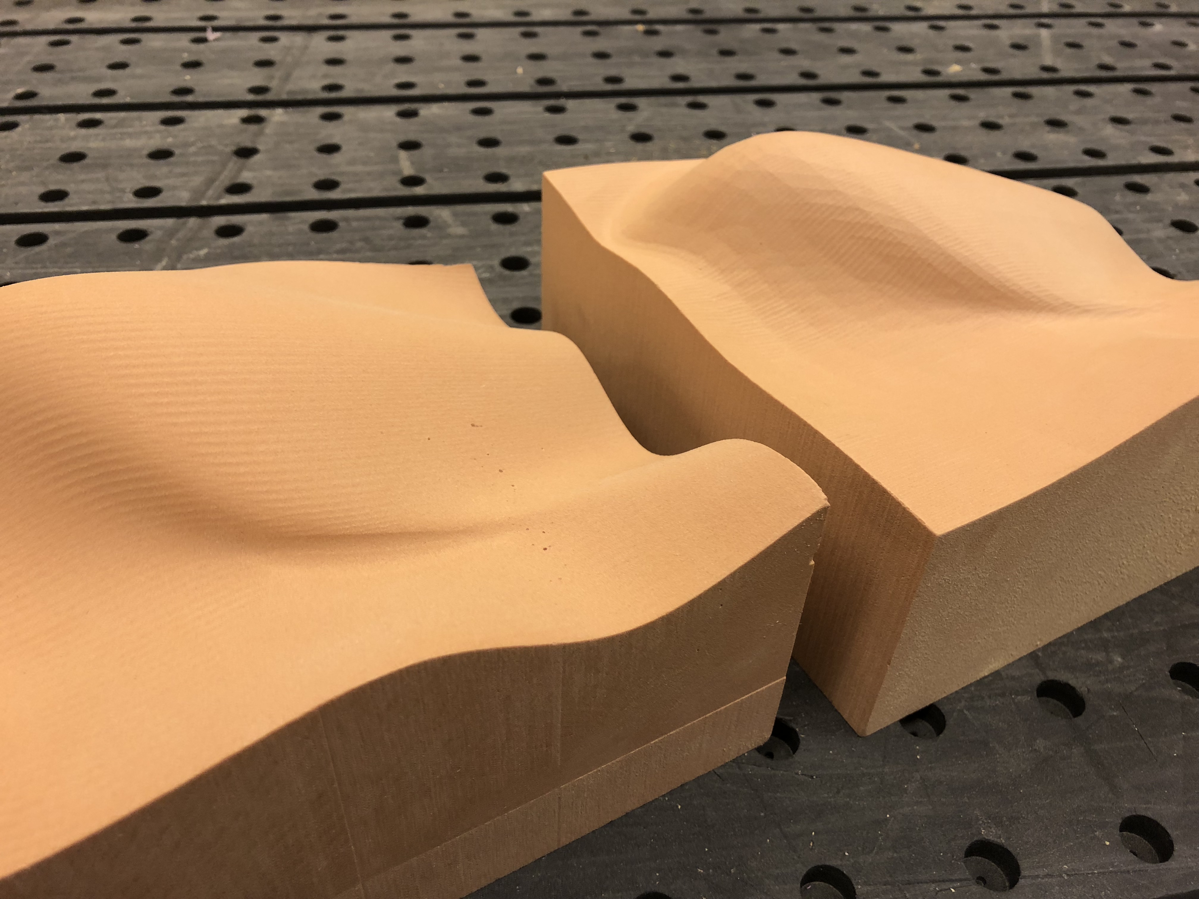
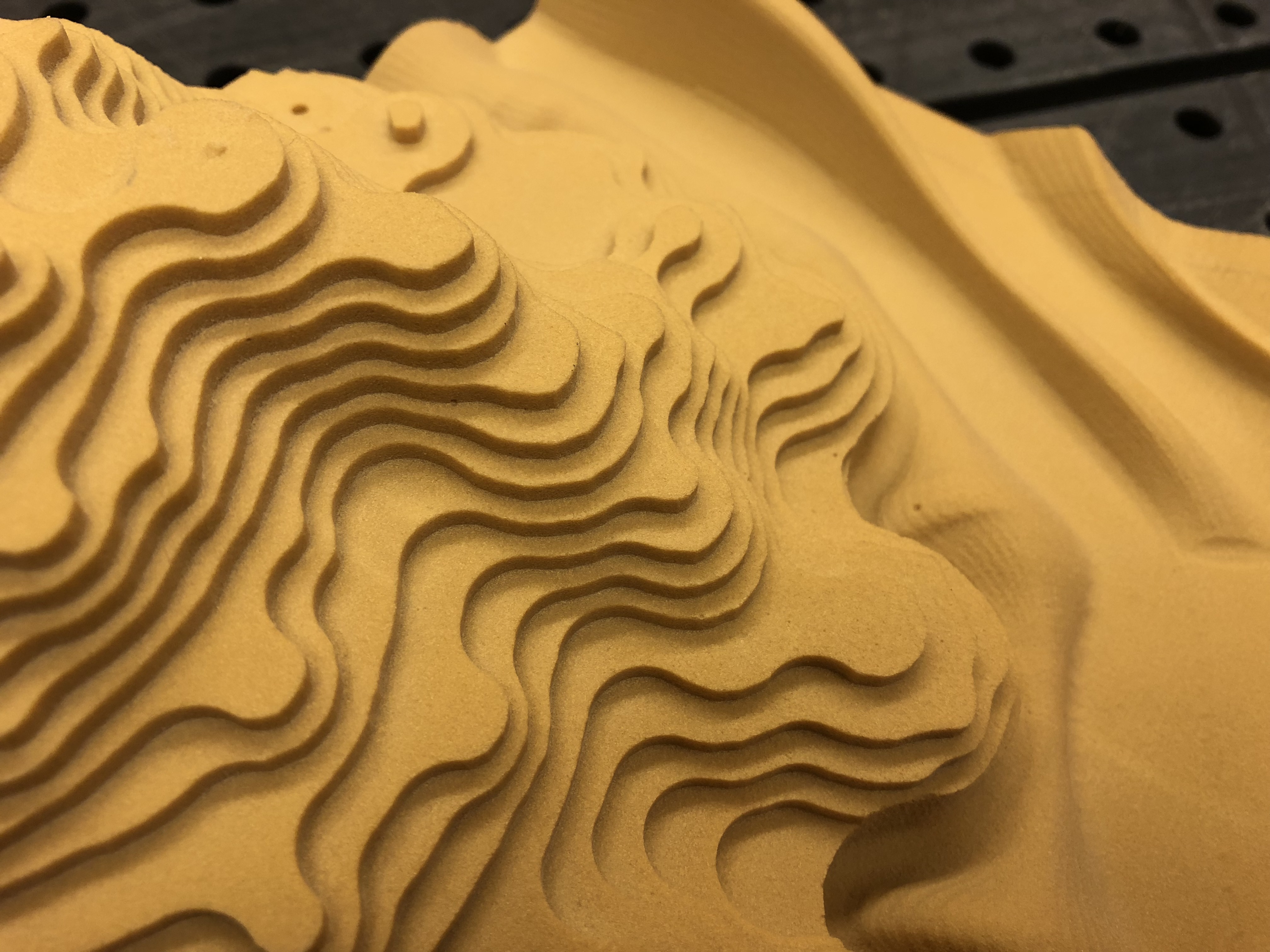
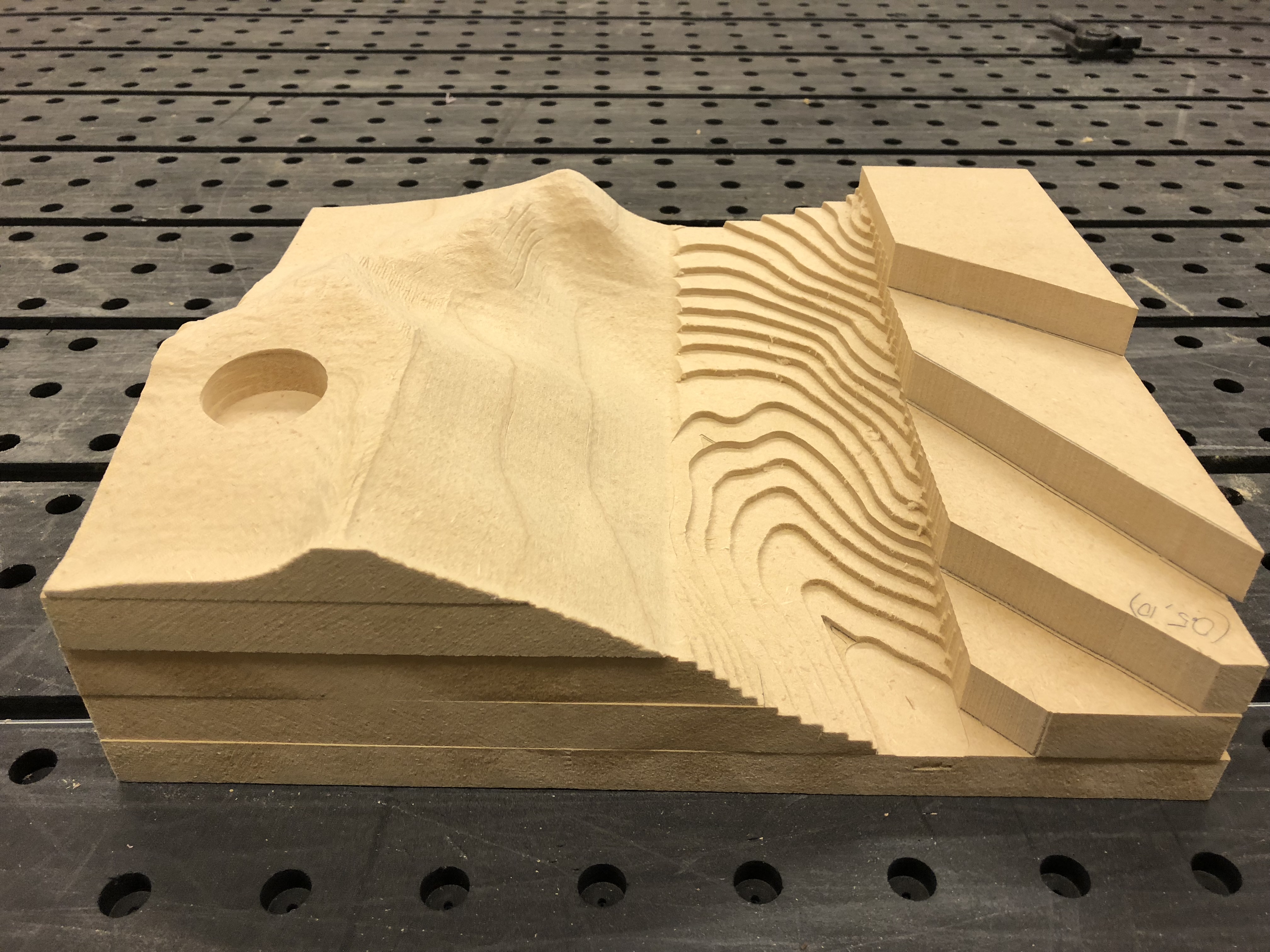
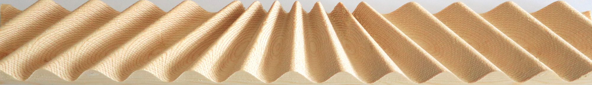
Example Work