A breakout for the MAX 30105 on Sparkfun introduced me to this chip family from Maxim. 30105 detects smoke using IR, Red, Green LEDs to illuminate the surroundings and a photon detecter to sense. The cool part is that the the light source and the detector are part of the IC package, along with an ADC, LED driver electronics. The sensor output to microcontrollers is through i2c.
As it turns out, Maxim has a couple of other chips (MAX 30100/1/2) in the same family, which work on the sample principle but are specialized towards measuring heart rate as well as SpO2.

(oops, sorry Premier Farnell – Totally non commercial purposes)
The easiest way to prototype would be to use a development kit offered by maxim, but unluckily the board is not in stock, and will take atleast 6 weeks for the shipment to come in. Maxim was really kind to offer me free samples of the MAX 30100 and the 30102, so the next logical step was to make my own breakout board.
Sadly, the package is non standard and features an 0.8mm pitch necessitating the need for a custom breakout board and a stencil to solder the component to the PCB using reflow. I relied on my trusty purple gold PCB supplier, OSH Park. I made the OLGA chip package for Eagle myself, so I’m not sure if it turned out right. I guess I’ll cross the bridge when I get there.
I was too cheap to order a breakout from OSH Stencils, but I could possibly use the Eng Phys project lab laser cutter to make a very basic mylar or kapton stencil.
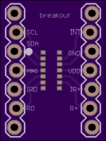
As I dug more into the datasheet of this IC, I found that it shared a lot of similarities with the MAX 30105 – The chip used in the sparkfun breakout. I just decided to send the eagle brd files (which are open sourced under OSHW licensing – I owe Nate Seidle a beer when if I ever meet him) to OSH park as well as get a kapton stencil at OSH stencils. There’s some level converted circuitry on the breakout as well as a 1.8V SMD LDO. As I have not broken into my SMD reflow/hot air rework setups yet, I think a combination of the simple breakout shown above and circuitry on the breadboard has the greatest chance of success.
I’ve been thinking about how to miniaturize this system if it works, and here’s my thoughts on the topic
- Integrating it into a fitness band/watch form factor is useful to make it unobtrusive and ensure compliance.
- The round face can be as large as the 3V/3.3V coin cell battery required to power the system. Alternatively a LiPo battery can also be used. If a LiPo battery is used, a battery management IC needs to be used.
- A low power microprocessor capable of I2C
- A high frequency speaker and a high intensity LED.
- The PulseOx would have to be on the opposite side of the battery and the electronics, on the wrist.