Developing with the ESP32

Standard

IoT is a field that I’m intrigued by, one that I work in.

As a member of the Vancouver Hackspace, I have had my eyes opened up to open-source alternatives to many proprietary technologies used in the contemporary IoT space. Kicad and Eagle for Printed Circuit Board design is one that comes to mind immediately, and so does ESP32 vs. Particle for a cloud gateway.

At work, we use Particle as our IoT gateway of choice. They build hardware while navigating the supply chain issues facing the industry, manage the cloud infrastructure, provide for OTA upgrades and fleet management. For all this they charge a reasonable premium to justify their valuation 🙂 The justification to go for particle from a work perspective was to shorten development timelines. Time is money, when you have folks on the payroll and no revenue incoming therefore you look for ways to get to market/revenue as fast as you possibly can. Fun fact, the particle folks use the ESP processor to manage WiFi!

On the other hand, the open source IoT world uses ESP32. In terms of capability, the ESP is equivalent to the Particle. The development tools are well built, however need some time to setup and extract the most out of. As someone who is not a developer per se – In my current job I’m managing product/projects/funding/sales/deployment in addition to a bit of development, I’ve never gotten the time to really learn to become a power user of a particular device.

Stating the intent here that I’d like to become the power user of an esp32 just for knowing that I can and laying any impostor syndrome feelings to rest. It would be good to focus on the development workflow (bring state of the art software practices to firmware) rather than hardware for a little bit.

I’ve ordered a dev kit and a debugger. I see some nice YouTube videos on setting a development environment up in VSCode. I’ll be trying to do that!

DIY Gel Doc

Standard

The lab was looking for a simple non-UV gel doc system after we got the DNA electrophoresis setup. EmbiTec sells a cheap (~1K USD with camera, 600 without) gel doc system that lets one take images simply with a camera or even a mobile phone. Could I take the major themes from this product, and build one really quickly (and cheaply)?

It simply consists of a black plastic box that provides the necessary focal length for the camera to focus on the gel that is placed on a glass bottom that is illuminated with the necessary LEDs to excite the DNA dye. Optionally, an amber long pass filter can also be used to increase contrast.

I first made a box out of black poster sheets from thorlabs that was lying around in the lab by laser cutting. I definitely need to automate the process of making 3D objects by using slots in 2D sheet material. Maybe solidworks can help with this. Need to learn! Once assembled by aligning the slots with the holes, the edges were simply glue together to produce a reasonably strong and optically non-reflective box.

This box was sized to fit the 385 UV lamp that we currently have in the lab, but it was observed to be too strong when used with the gel. It’s too bad there isn’t any intensity control. Also, we needed a diffuser since the the LED’s in the lamp are large and discrete. When this didn’t work, I started thinking about using a tracing light box/surface as the light source. 

Taking it apart revealed a few interesting things and increased by already high mad respect for chinese engineering. The device simple consists of a row of white LED’s (with 68 ohm resistors) all connected in parallel to voltage rails. The voltage across these rails can be cycled through 2.6V, 3.3V and 4.4V by tapping on a capacitive switch (no BOM, all in PCB design itself!) connected to an 8 pin microcontroller. Would love to reverse engineer this when I have time. But going back to the original task at hand, I needed this box to now generate a diffuse uniform blue back-light.

Doing this called for a couple of modifications, the white LEDs in the PCB had to swapped out for specific LEDs that are capable of exciting gel green (the DNA dye). Gel green has an excitation peak at 500nm, and an emission peak at 530nm. Sadly, 500nm is right between blue and blue-green, so I couldn’t find an LED on digikey that had a coincident emission peak.

Image result for gel green excitation spectrum

I settled for the SMLE13BC8TT86, which is an InGaN LED that emits at 470nm. It is available in an 0603 package, whose footprint is close to the footprint on the PCB of the tracing box. Assuming a forward voltage of 3V. Using the 68Ohm resistor at the high voltage rail setting gives an approximate forward current of 20mA (almost close to the peak applicable current). Increasing intensity would mean a decrease in size of the light box and a density increase.

An image of a gel frame with the dark box and the modified LED array looks like this

First reflow with my workbench

Standard

I’ve recently started building my own workbench at home, and I just turned my first board out after solder paste reflow using a rework station. It was beautiful. I did not have a few components required (the design was based off sparkfun’s breakout for the MAX30105), so I winged it a bit. Pullup resistors are not 4.7k, but 5.1k and a few decoupling caps were 10uF instead of 11. The circuit itself simply has two bidirectional level converters, and a 1.8V voltage regulator acting as peripherals to the pulse oximeter chip.

A couple of things I still need to work on though

  • Getting an ESD safe bracelet and mat
  • Which is also heat resistant – I almost burnt the wood on the table I was working on.
  • Get a smoke evacuator AKA not die of lead poisoning/cancer.

I’ve been mulling over the idea of making my workbench accessible to people with open source electronics. Something similar to pro-bono work.

Disc golf and blinking LEDs

Standard

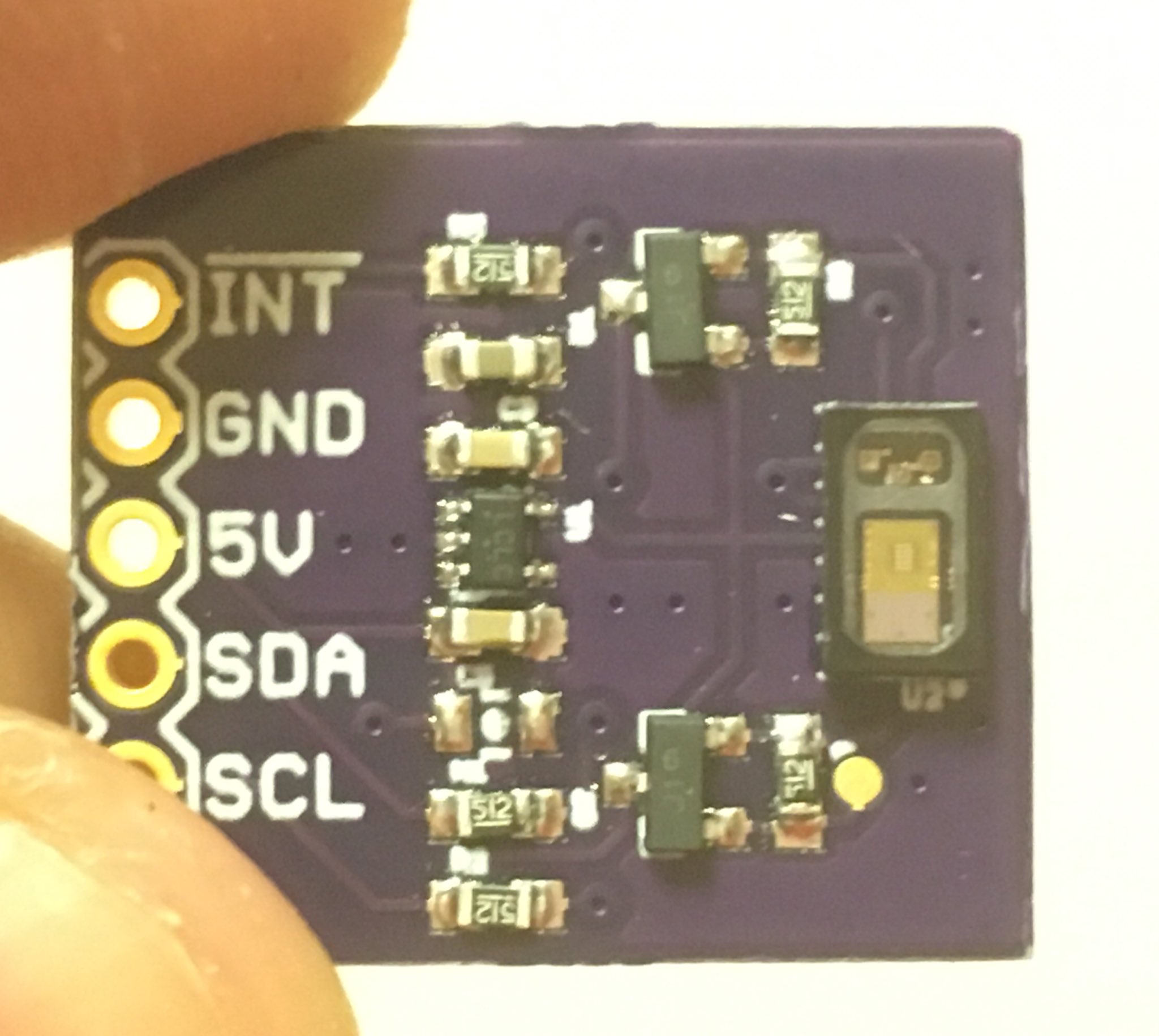
Sydnie introduced me to disc golf, which is a really cool sport. Think golf, but replace the clubs and the ball with frisbees. Vancouver, well being vancouver has quite a few disc golfing courses (which also double up as public parks – disc golf isn’t elitist). When winter sets in at the 49th parallel, it can get dark pretty early in the evening. Some amazing soul came up with the idea of putting LEDs on discs to light them up at night.

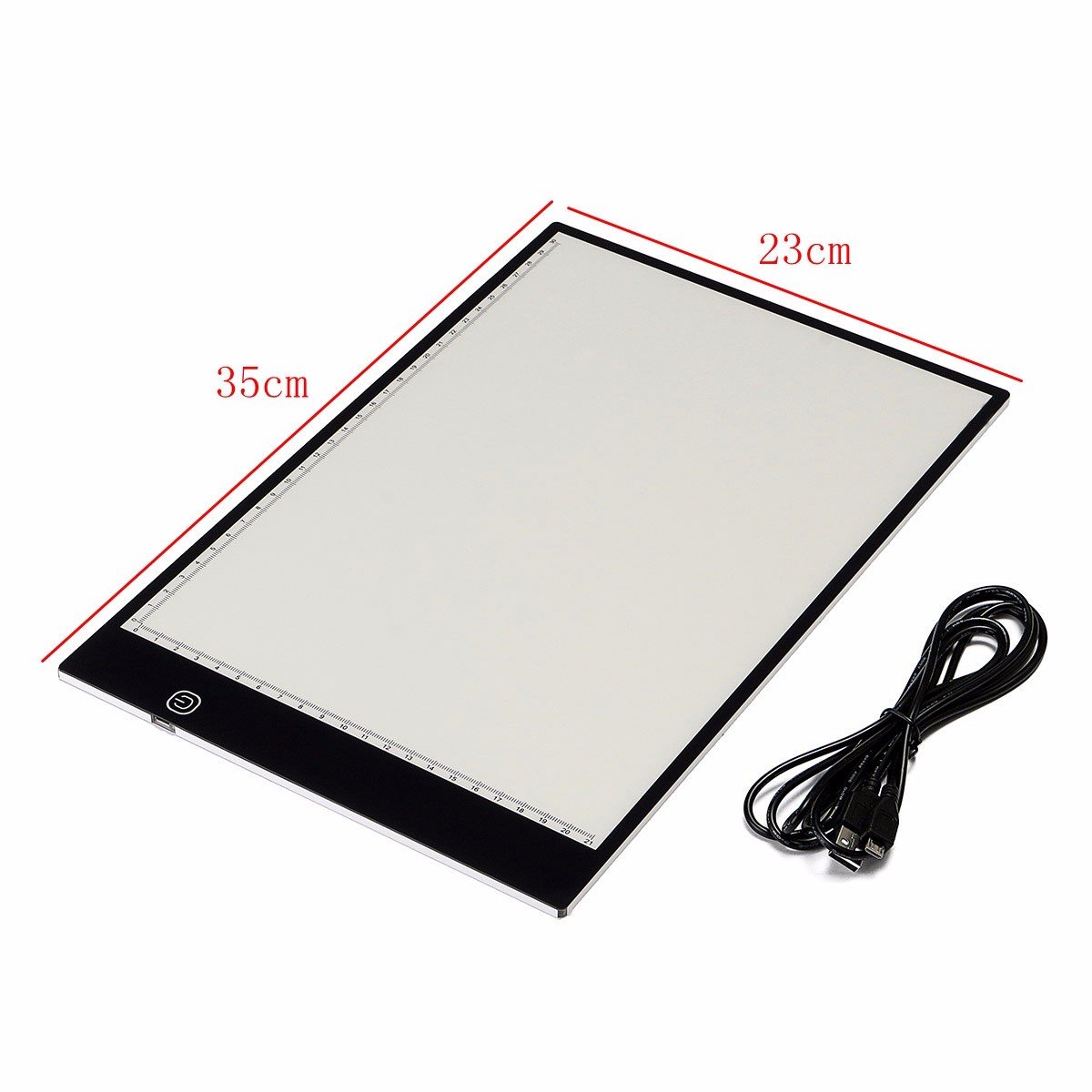
Sydnie has a bunch of them, and they’re really similar to these you can get off amazon. They’re powered by a coin cell battery and have a tactile switch that can toggle between 4 states – OFF, always ON, fast blink and slow blink. I was super impressed that all of this could be done under a price of 25$ for 12 and in that form factor. The bill of materials for each piece was definitely less than 1$. The engineer in me wanted to replicate this, and I set with much academic naïveté.

I knew the circuit definitely had

  • A dual 555 timer or equivalent to enable blinking at a slow and fast rate
  • A CR2016 battery (as mentioned in the battery specs)
  • A tactile switch
  • An LED

As engineers are always wont to do, I wanted to better the current specs and put in an RGB LED whose colors could be toggled through and blinked at different rates. I still wanted to theoretically make it cheaper than the amazon price, so $2 was my limit. There was no way and design could could come under that limit if it featured a micro controller. (An attiny85 itself costs $3 in singles). I would have to stick to using some kind of a digital IC.

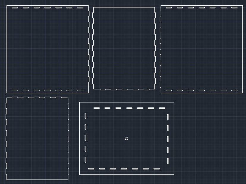
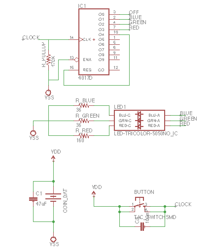
An initial idea for a prototype that toggles through multiple states involved a decade counter. A decade counter IC pulls one of its 10 pins high in increasing order when it receives a clock pulse as input (detects the positive edge). A momentary tactile switch (with a capacitor across to prevent key bounce) could be used to pull up the clock pin to VDD from ground through a pull up resistor. As each of the pins of this decade counter can sink more current than the rated supply current of the LED, no additional circuitry would be required. 3*3 pins for (R,G,B)*(ON, Fast Blink, Slow Blink) and 1 pin for OFF. The plan sounded great in principle. I started making the schematics and routing the signals on a dual layer PCB. There was no way I could get this fit in the footprint of a CR2016 battery (which was a vague yardstick and also because I could get a circular PCB). I was definitely doing something wrong in my design.

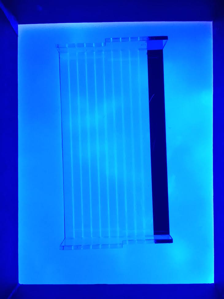
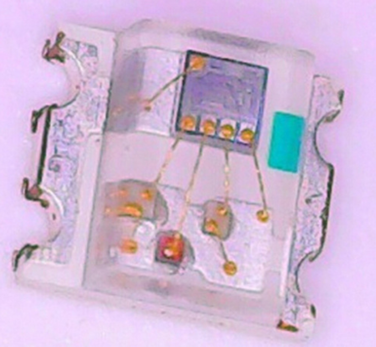
However when I held Sydnie’s LED against bright light, I couldn’t see any circuitry other than the LED module, switch and the the battery terminals. There were only traces on the PCB. When i looked closely at the LED, it seemed to have too many components on the die for a single color LED. And then it clicked… the 555 die was wire bonded directly to the LED. Putting both dies on the same substrate and wire bonding them together results in a far smaller footprint than laying out a PCB and routing them external to the package. (as an aside, I was listening to the macrofab engineering podcast the other day where there’s a company trying to make systems in chips for products such as the beaglebone, cool!).

I tried finding LEDs with timers integrated, but I was probably using the wrong search terms, nothing turned up. Serendipitously, during one of my good for nothing jaunts on aliexpress, I found flashing/blinking LEDs! They look totally similar to the non flashing ones.

The LEDs I’m getting

  • 60pcs blinking solid smd 0805 LEDs for 5.5CAD (fast blink)
  • 100pcs 3mm blinking RGB DIP LEDs for 2.7CAD
  • 50pcs 0807 RGB LEDs for 6.35 (slow blink)

Ideally, connecting these LEDs to a switch and a battery is all I need to do!

But the engineering doesn’t end there and that’s the most fun part of it all. OFF-ON switches are way more expensive than simpler OFF – momentary ON switches and this makes a huge difference especially when cost is a huge specification. An OFF – momentary ON switch can either produce positive edge or negative edge clock pulses and these can be used to turn a JK flip-flop’s output high or low.

Lines in BOM

  • Tactile switch EG4621CT-ND – 2.86 CAD per 10
  • JK type flip flop 296-31493-1-ND – 5.22 CAD per 10
  • ON – OFF switch – 10.7 CAD per 10
  • Battery holder CR2016 – 4.1 CAD per 10
  • Batteries CR2016 – 9 CAD per 25
  • 470 Ohm resistor – Negligible
  • LED – negligible
  • PCB – Assuming OSH park medium run at $1/sq inch – 3 CAD per 10

Total price – 18.78 CAD per 10

YAY!


Opioids and Vital Signs

Standard

Even before Rohit messaged me with a problem statement on developing an early alert system on the opioid crisis (which converted an academic interest into a tangible goal), I was intrigued by the effects of opioids on the nervous system and breathing in particular. I found this really cool review paper talking about the specific mechanisms of opioids binding to receptors in the parts of the brain (the brain stem) known to influence respiration.

The questions I’m asking myself

  1. Once a drug bolus is injected intravenously, how long does it take for the drug to reach the target receptors in the brain stem?
  2. What is the time delay between receptor binding and apnea (cessation of breathing)?
  3. By how much time does hypoxia lag apnea?

Coincidentally, my roommate Ryan is a PhD student in zoology working on the nervous system control of respiratory rate (specifically hibernation) in murine models. When I directed these questions to him, I found out a few facts that surprised me.

  1. The opioid binding to receptors is immediate once introduced into the blood and so is the respiratory depression.
  2. However, loss of consciousness can occur before the SpO2 drops, which might mean that pulse oximetry itself is redundant as an early marker.
  3. The drop in SpO2 is sharp with respect to time.

Respiratory rate and pulse oximetry are therefore crucial signs that need to observed post OD. As a change in respiratory rate precedes one in SpO2, an early detection system must rely on the former. Respiratory rate can be measured through multiple invasive methods such as capnography (measuring CO2 concentration in the expired volume) and impedance capnography (4 probe electrodes on the chest which measure impedance change). However, I came across the Nellcor technology from Medtronic-Covidien which is a software that calculates the respiratory rate using nothing but the photo plethysmograph (PPG). They allude to observing changes in the baseline value, amplitude and frequency in the pleth waveform, assigning weights and averaging over a 40 second interval to compute respiratory rate.

I found an academic abstract that discusses respiration induced variations in the PPG waveform which concludes that amplitude variations correlate with the respiratory rate. However, this correlation is confounded and overshadowed by motion artifacts. Applying excessive pressure through the pulseOx sensor has similar effects.

To conclude, a pulseox vital signs system can and should definitely be prototyped as a possible solution to early diagnosis. The next few posts will focus about issues such as human centered design, user compliance and technical details of the prototyping of a PulseOx system.

Addressing Fentanyl ODs in Vancouver

Standard

r/vancouver is my go to place for all the local news. A recent post gave me a huge jolt. 9 people had overdosed on drugs in a single night. Drugs such as heroine and cocaine are being increasingly cut with fentanyl to increase their potency. As the amount of fentanyl can vary from batch to batch, a “safe” dose could easily cause a user to overdose.

As a reactive measure, the civic authorities have started programs to educate users and the general public about fentanyl, signs of an overdose and safety precautions. At-risk users are also given a Naloxone/Narcan kit for free, which counteracts the effects of the drug.

(BC Coroners service)

Clearly there has been a downward trend over the latter half of 2016 ever since a public health emergency was declared in April. As of October 27th, 2600 Naloxone kits have been distributed by Vancouver Coastal Health. Additionally, the Provincial Health Safety Authority (PHSA), through the British Columbia Center for Disease Control (BCCDC) has a take home Naloxone program which has handed out approximately 6,000 kits so far.

In an ideal world, everyone at risk of a fentanyl overdose would be next to a bystander carrying a naloxone kit. Sadly this isn’t the case. In a real world scenario, identifying the signs of an overdose and reacting to it faster could save more lives. As a working hypothesis, I think that a vital signs tracker and alert system given out for free to the population at risk can substantially reduce fentanyl OD deaths.

A technological solution/road map furthering this hypothesis will be presented in the next post.

A Moleskin

Standard

I’m schizophrenic, but not in the clinical sense of the word. I brew freshly ground, recently roasted coffee in an aeropress with temperature and weight control while also enjoying a cup of Indian instant nescafe with milk and lots of sugar in the morning. I love good sourdough, and I’m experimenting making my own Idli and Dosa batter. By the way, this is unrelated to the topic of this post. Or not.

My planning’s ratchet, but I have this inexplicable urge to use a Moleskin book. I believe it has something to do with a visit to the Computer history museum in Palo Alto. The bay area is an amazing place. It’s almost as magical as it’s made out to be. The museum displays include pages from William Shockley’s laboratory book. Such revolutionary ideas casually written on single pages.

I gifted myself a Moleskin (with Amazon store credit from my Uncle). I hope this helps in my research. Just today, Hong and I came up with some pretty sweet ideas for my research. They’ve been dutifully added to Molly. May this blog post serve as a reminder of the approximate time frame I started keeping research notes.