Airflow sensors, especially in the domain of sleep diagnostics, measure respiration rate and flow in general use thermistors as the temperature sensors. Each airflow sensors consist of three thermistors, positioned at each nostril and over the mouth. Thermal airflow sensors work on the principle of the different temperature of the ambient air while breathing in (ambient air temperature) vs. breathing out (37 degrees).

Sensors available on the market are mucha expensive and possibly proprietary connections leading to bulky connections. Might make sensor to build our own.
The base sensor that we are choosing to use is a glass encapsulated DO35 package through hole thermistor from digikey.
Some characteristics
- DO-35 package (JEDEC Standard)
- Glass encapsulated
- Resistance of 50K at 25degrees C
- Time constant
- 5 seconds (Still Air)
- 0.5 seconds (Stirred Liquid)
- Response time of air with convection should lie between above limits
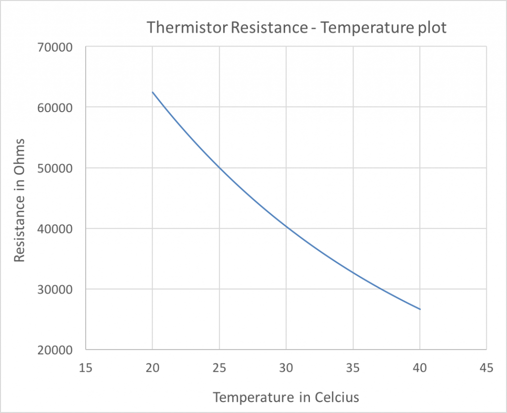
- RT curve is shown in the curve below
- 55K at 23 degrees C
- 30K at 37 degrees C
- 20mW maximum power
- Current through thermistor must be less than 0.8mA (800uA)
- With a 47K resistor in series, currents are on the order of 60uA (well under 800uA limit for max power)
 Implications of these characteristics
- Sensor head is approximately 5mm wide
- DO35 footprint on PCB is also ~5mm
- For 5 second response time, sensor can detect 12 temperature changes a minute, or 6 breath cycles (each breath cycle is temperature increase followed by a decrease) – 6bpm limit
- For a 0.5s response time, RR limit is 60bpm
- Including the thermistor in a resistance bridge (with 47K ohm resistor) to function as resistance to voltage converter, the output voltage changes from 2.7V@23 degrees to 1.94V@37 degrees
- Increase in ambient temperature leads to to a decrease in output voltage range
- It is also important the the current through the thermistor be as low as possible to avoid any resistive heating effects that cause a temperature change
Thermistor circuits
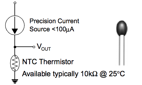 Using a precision current source is the right way to exploit the Resistance-Temperature relationship of a thermistor.
However, we do not require absolute temperature but rather relative temperature changes. As such, simply placing a 47K resistor ensures that the currents are within the max power limit, and that the output voltage has substantial change.
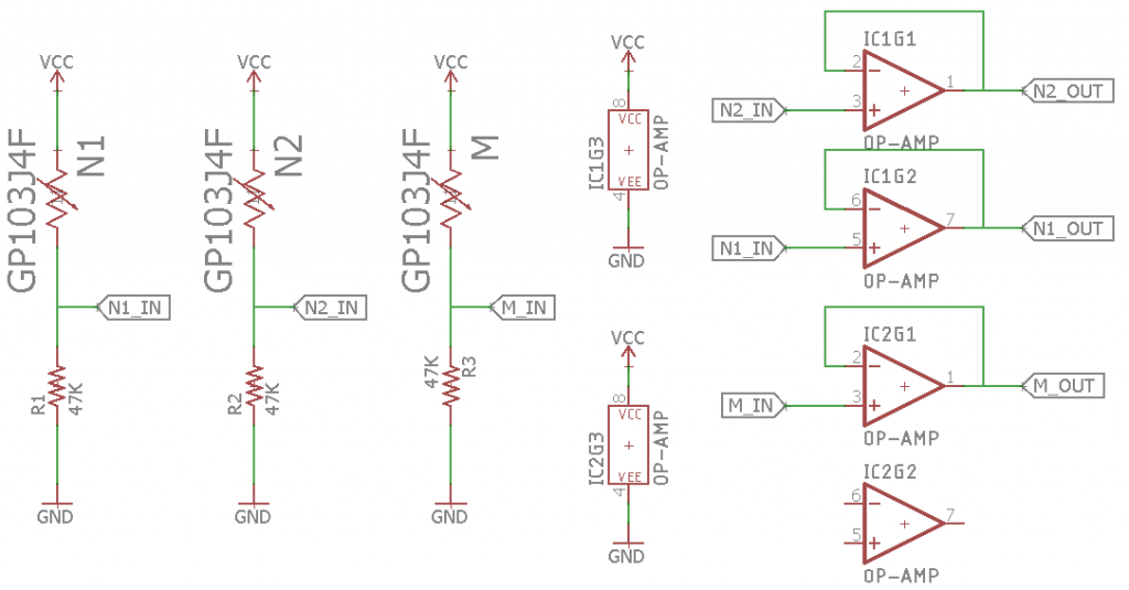
Using an opamp however as a buffer block (negative feedback with gain 1) can prevent any loading/interference on part of the microcontroller circuit
Test circuits
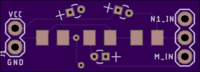
- Wearable #1
Features/Specs
- Designed for wires to be wound around ears. Header/wire connections at either end.
- 2 separate thermistors for nostrils (15 degree angle, 0.3′ apart)
- Thermistor for mouth airflow temperature
- Simple Resistor bridge circuit
- Thermistor is the GP103J4F
- 1206 resistors (10K) – Easy manual solderability
- Ordered on 13 Nov, Oshpark Swift, free shipping
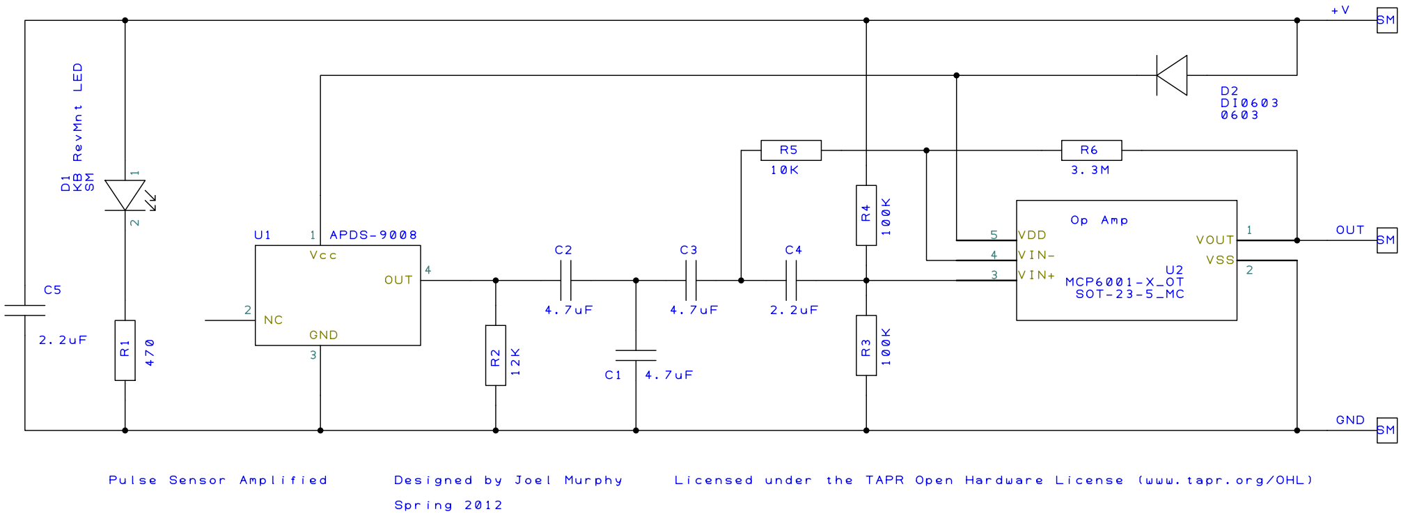
2. Breadboard #1
Features/Specs
- Thermistors
- Through hole resistors
- DIP opamp