The Breakout PCB’s came in from OSHpark today, and so did the stencils from OSHstencils. I ordered 6 boards in total, 3 with the larger AMS1117 regulator, and the others will the much smaller SOT23-5 package. The stencil for the latter was made with the engphys laser cutter using the gerber files and inkscape.
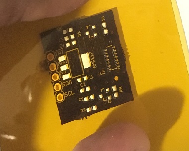
The intended use for this breakout is a platform to use/modify the sparkfun MAX30105 (particle sensor) library for the MAX30102 (pulse ox) chip. This board can be considered the sensor layer v1.0. If required, a temperature sensor can be added on the same board with minimal modifications since the level conversion for the I2C and the power regulators are already on board.
Now that the sensor layer was taking shape, I began thinking about the other layers though which the physiological data had to pass through before it could be acted upon. From a bird’s eye view, the system has three main layers
- The sensor layer to acquire data
- The uController layer to process this data
- A Power management layer
- User Interface layer to interact with the used
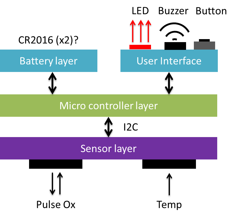
Based on the conceptual framework that I’ve drawn up, the microcontroller layer would be physically sandwiched by the sensor layer and the battery/UI layers, primarily because the user does not interact with this layer directly in any way (higher level of abstraction). The top layer board will simply be a CR2016 holder or a JST header, with the LED, buzzer and button surrounding the battery footprint. The reason I’m looking at coin cell batteries (CR2016 is 3V, 100mAh) instead of LiPo (usually 3.7V, variable mAh depending on size) is the ability to replace them for cheap, unlike LiPo batteries which can be recharged but are expensive. However, if a LiPo solution needs to be prototyped, then the Adafruit LiPo battery backpack could simply be used.
For the purposes of prototyping, the microcontroller layer can simply be a Adafruit Pro Trinket. It has a footprint of 38mm by 18mm, with an microUSB port for simple reprogramming of the atmega328p. However, the FTDI port will have to be used for communication through the serial port. At the very early stages, and Arduino Uno would be a better prototpying platform (#ObviousOstrich) Though the Pro Trinket is rated for 5V operation, it can work with a 3.7V supply, though the system would not be very robust.

The image above shows a 100mAh LiPo battery connected to the battery management breakout board in the corner, which sits on the microcontroller board.
Building a prototype with a small form factor while including all the desired functionality will require some clever solution to connection to connect these multiple breakout boards to each other. This is a critical step before redesigning the board to include all the components on the same board. Thinking out loud, I can come with flex cables as a possible solution. The ones you see in mobile phones are way out of my league, flex cables with TE AMP connectors might be plausible.

A 2 inch length FFC connector with 4 solder tabs costs around 70cents and is custom made by digikey. A crude but effective solution might be to solder small gauge wire between the boards directly.