
Fig. 1 – Solar-powered tricycle, Daisy, at Burning Man
Introduction
The Capstone project is usually done during the final year of your engineering degree. Each department get projects provided by companies related to their areas of expertise. For UBC Mechanical Engineering, the projects range from fluid dynamic pipe flow testing, biomedical knee braces, to rovers that fix wind turbine blades.
All the potential projects are presented to you in the first week of September. Then you’re allowed to rank your choice of top five projects. I was matched with my second choice, eatART Daisy Drive project, along with three other Mechanical Engineering students. The eatART (energy awareness through art) foundation is a not-for-profit foundation composed of volunteers from the STEM and art fields. Our client is the Co-Executive Director who is also a mechanical engineer and UBC alumni. Our project is to optimize the design of the electrical belt drive of the largest solar-powered tricycle in the world, Daisy.
Built approximately 20 years ago by inventor Bob Schneeveis, Daisy traveled to Burning Man, an annual festival celebrating community and art and was used to drive passengers around using purely solar power. At its maximum capacity, Daisy can carry four adults in its carriage plus a driver in the front. It is steered by a hand crank and speed-controlled by a foot pedal throttle. Due to its size and weight, Daisy has only been able to travel on flat ground, such as the desert where Burning Man takes place. Now that Daisy is in the possession of the eatART foundation in Vancouver, our aim is to improve Daisy’s climbable incline so that it fits in with the hilly terrain of Vancouver.
First Term Steps to Capstone
1. Define value for stakeholders. Establish scope of your project.
Since our team is working for a not-for-profit organization, our project’s value is in the social-good generated rather than monetary value. With an optimized drive system, Daisy can be used in Whistler village, where roads are at a slight incline. Allowing Daisy to carry visitors in Whistler allows the eatART foundation actively showcases the accessibility of renewable energy technology such as solar power.
Initially, our client mentioned that the major design issue is in the V-belt that translates the motion of the rotating motor shaft to the three meter tall front wheel. When the V-belt slips from the sheave, this means that despite the motor still turning, the wheel stays stationary. This is particularly dangerous on an inclined road, since the front wheel will start to slip backwards without braking. Even with brakes applied, Daisy remains stuck on the inclined road, and cannot move forwards at all.
Another mechanical design flaw was in the belt tensioning mechanism. This mechanism provides tension in the V belt by pulling the two sheaves apart further. This is currently done by winding up a torsion screw attached to the motor and the front frame. This tensioning system doesn’t seem to be properly designed and may be experiencing induced strains and stresses. By redesigning the tensioning mechanism, we could eliminate these stresses and eccentricity, allowing the sheaves to be correctly positioned relative to each other.
To climb a hill, a certain torque is required. Imagine changing to a smaller gear on your bike while climbing a hill. You slow down significantly, but it becomes easier to pedal. A smaller gear ratio means that speed is traded off for torque. Similarly, the current motor and gear configuration could not provide sufficient torque to climb any incline because the gear ratio was too big.
Limitations also arise from the electrical system, as the batteries only provide 24 volts, the motor controller seemed to be old and out-of-date. The motor’s torque capability sets another limit. Its peak torque (stall-torque) and power could be simply insufficient to move the large tricycle.
To sum up all the aforementioned design flaws, they include:
- V-belt slippage,
- belt tensioning device,
- low gear ratio,
- and electrical power limit.
2. Investigate the problem. Define functions of your solution.
Since Daisy was quite old, the information on its components were not recorded well. Through testing and investigation, we collected data on the electrical motor, the motor controller, and the drive.
For instance, we tested the efficiency of the motor controller. Running the motor without the V belt attachment, we measured the input current from batteries to the controller, and the output current from controller to motor. Then, the power was calculated from the simple P=IV equation. The ratio of Pin / Pout represents the controller’s efficiency. Since Daisy has a throttle, we ran test trials by varying the power draw from motor, from 17% to 100% of power draw. The controller efficiency we calculated is represented in the graph below.
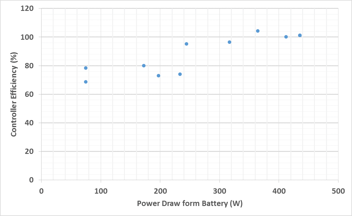
Fig. 2 – Controller efficiency as power draw from battery increases
Evidently, the controller efficiency was above 60% at all times. More importantly, the controller was operating at 100% efficiency near the max power draw from motor. We concluded that a replacement for the controller was not necessary.
3. Conceptualize different solutions.
After defining the functions required to perform by your solution, create various concepts through simple sketching. Aim for quantity instead of quality. You want as many concepts for each function as you can. These become your concept fragments; they are fitted together into whole concepts through mechanical mounts.

Fig. 3 – Concept sketches; (on left) treads with timing belt; (on right) pedal chain drive
After attaining several whole concepts, you should evaluate them on a impartial basis through winnowing, Pugh chart, and a weighted decision matrix. We evaluate our concepts based on a variety of performance metrics, one of which essential to any project is cost. Even though our team had lots of different concepts involving electrical components, they did not do very well in the cost criterion of the Weighted Decision Matrix. In the end, we ended with two concepts with good potential, the chain drive and added traction on wheels. The two-stage chain drive concept we came up with would eliminate slippage and increase the effective torque translated.
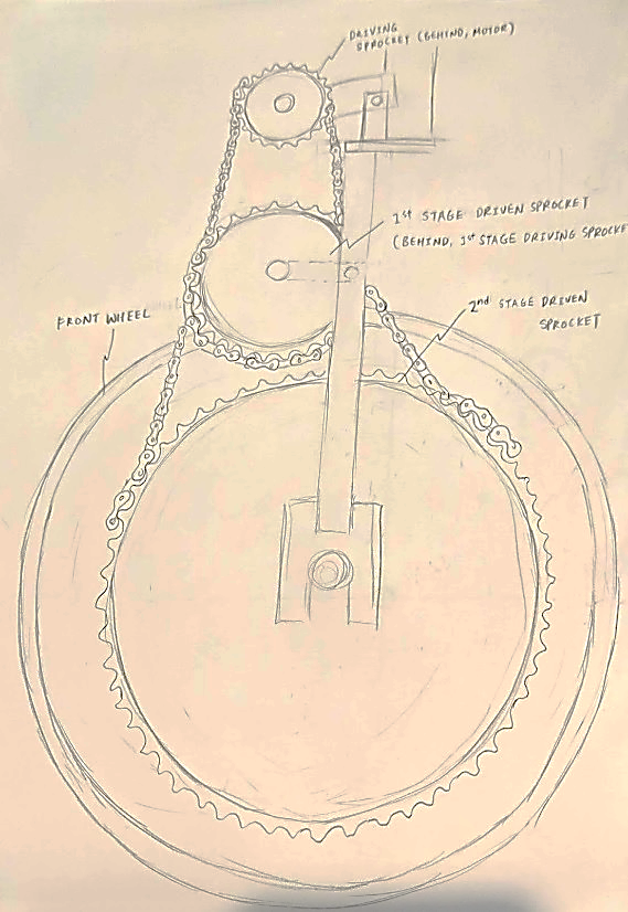
Fig. 4 – Two-stage chain drive concept sketch
As opposed to a single stage chain drive, two stage would allow a much greater gear ratio while staying within the recommended roller chain to sprocket contact.
4. Create a critical functional prototype (CFP).
The critical functional prototype (CFP) is designed around a selected function that’s critical to your solution. This is a great chance to see the physical (not theoretical) feasibility of your concept without investing resources into the whole concept. The CFP also allows you to detect unexpected failure modes, undesirable defects, and incalculable performance issues.
We needed to confirm that a chain drive can sufficiently translate motion from motor to the wheel, so we built a chain drive prototype consistent of a motor, a driving sprocket and a driven sprocket. The gear ratio (# teeth driving / # teeth driven) is 17:73 or approximately 1:4. We also set up the different transverse offset to see the upper limit at which the chain starts to derail, rendering the drive useless.
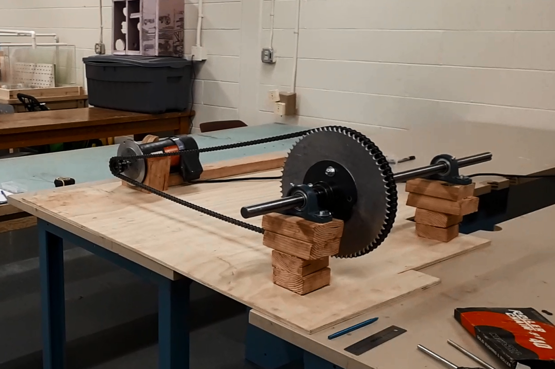
Fig. 5 – Chain drive critical functional prototype test rig
The motor was running at different speeds with light shocks applied. What we found was that for commercially made sprockets (with special profiled teeth), there was almost no derailment at any transverse offset or motor speed. However, for the water-jetted sprocket, there was almost always derailment. Upon closer inspection, the aluminum plate may also have deformed while in storage, so the sprocket it made was slightly bent, leading to the chain derailing.
5. Reiterate the design
After presenting to the client once more with our CFP experiment results, the chain drive concept was deemed too risky to implement. It would increase the number of mechanical components, and due to lack of slippage, could cause irreparable harm to the motor and electrical components if the drive gets jammed.
The concept we ended up with is increased traction (through additive materials and increase wheel width) and better tensioning of the driving pulley to eliminate V belt slippage.
Through preliminary calculations, we also discovered that the batteries shifted a lot of weight to the rear of the tricycle. On a hill, this would create a lifting effect on the front wheel. By shifting the position of the batteries closer to the front wheel, we could better distribute Daisy’s weight and give it more grip on the road.
We decided, along with the clients, that a prototype wheel should be built to test different traction materials such as truck bed liner, spray-on rubber, and etching notches into the flat bar metal. We will be building a section of the wheel out of steel flat bar, attached to an electric motor at the same torque and the power level as the one on Daisy. Then we can apply the various materials onto the section and run it on a ramp. If the section successfully climbs the ramp, then it proves that the material provides sufficient power. If the section slips, then there is not enough traction. Oppositely, if the section is stuck, then there is too much traction force.
That’s all for now. The design process will resume next semester with fabrication.
If you have any questions, please comment down below. I look forward to chatting with you.
Cheers,
Kirsten